10-pin 1.27mm Arm ECU14 Debug Adapter
|
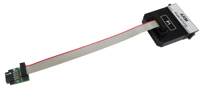
The ECU14 connector and the pinout has been defined by Bosch. This debug adapter is used to connect the iC5000 and the iC5700 BlueBox to Arm Cortex based target featuring a 10-pin 1.27mm pitch target debug connector with Bosch ECU14 pinout.
The debug adapter connects to the 25 cm 40-pin ribbon cable coming from the BlueBox and to the target debug connector on the other side.
|
This debug adapter supports only the JTAG debug interface. |

The following pinout is valid on the target side:
Signal Direction |
Signal Description |
Signal |
Pin |
Pin |
Signal |
Signal Description |
Signal Direction |
|---|---|---|---|---|---|---|---|
|
Ground |
GND |
1 |
2 |
TCK |
JTAG |
O |
O |
JTAG |
nTRST |
3 |
4 |
TDO |
JTAG |
I |
O |
JTAG |
TMS |
5 |
6 |
TDI |
JTAG |
O |
|
Not Connected |
NC |
7 |
8 |
Vref |
Reference Voltage |
I |
|
Not Connected |
NC |
9 |
10 |
nRESET |
Reset |
O |
10-pin Bosch ECU14 target pinout
Signal Direction is described from the BlueBox perspective.
|
When initially connecting the BlueBox to a target, ensure the debug adapter pinout matches the Target connector to avoid potential hardware failure. |
This Debug Adapter features resettable fuses on all connected pins. These protect debug signals against overcurrent and cycle back to a conductive state after the excessive current fades away. Mandatory pins on the microcontroller side are GND, TMS, TDO, TDI, nTRST, TCLK and nRESET.
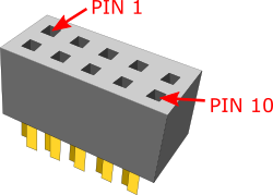
Pin 1 position
|
The pin next to the alignment pin is pin 10 and not pin 1! Pin is marked with a number 1 directly on the converter target connector. |
 |
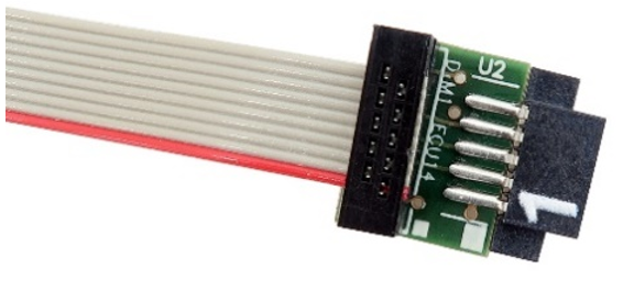
|
The pin 1 position is marked with a small white square on the PCB. Additionally, the pin is marked with a number 1 directly on the debug adapter target connector from revision C1 on. |
|
Make sure this adapter fits on your target connector - check Cross Table. |
|
Refer to Hardware Setup and Configuration Tutorial for more information on how to connect the hardware. |