Configuring BlueBox Hardware
In this topic:
•Connecting the BlueBox and PC
•Connecting the grounding wire
•Connecting the BlueBox and the Target
Introduction
In this tutorial, you will learn how to connect and configure:
•iC7 BlueBox (iC7mini/iC7pro/iC7max)
•iC5 BlueBox (iC5700/iC5000)
with the target via Debug Adapter and various Active Probes.
Connecting the power supply
Power connector is located on the rear side of the BlueBox.
1. Make sure the BlueBox is switched off.
2. Connect the power supply cable.

It is important to carefully push in (or pull out to disconnect) the iC5 power supply connector plastic sleeve into the BlueBox, as it features a locking mechanism.
Connecting the BlueBox and PC
BlueBox can be connected to a PC with USB 2.0/3.0. or TCP/IP.
To configure the TCP/IP connection, the BlueBox has to be temporarily connected to the PC via a USB cable.

1. Connect via USB.
Ethernet and the USB port may look similar. Make sure you connect the USB cable to the correct port.
|
When the BlueBox is connected to the USB port of PC for the first time, Windows will detect a new device and may prompt you for the driver for it. Go to troubleshooting section if you experience USB driver issues. |
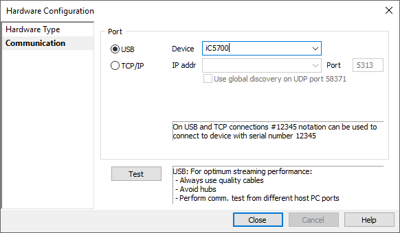
2. (optional) Configure the TCP/IP connection on the BlueBox and winIDEA side.
•BlueBox - Open Hardware > Debugger Hardware > Hardware Type > System Configuration. By default, the TCP/IP settings are obtained automatically from a DHCP server on the network. If such a server is not available, the settings can be set manually.
•winIDEA - There are multiple ways to connect to the BlueBox via TCP/IP port. Refer to Communication Dialog Reference for more information.
Connecting the grounding wire
With this step you set set the BlueBox and Target to the same potential.
|
If the grounding wire is not connected, the ground potential difference between the BlueBox hardware and the Target can exceed well over 1000V even before any of the devices are powered up. This voltage difference is discharged over the BlueBox hardware and the Target, potentially leading to the destruction of electronic components within both the BlueBox hardware and the Target. |

1. Connect the grounding wire to the BlueBox.
The Grounding wire connector pin is located on the front panel of the BlueBox and is marked with "GND".

2. Locate the ground potential (GND) on the Target and connect the test clip.

Connecting the BlueBox and the Target
Depending on the hardware configuration, the BlueBox can be connected to the target via: