10-pin TriCore ECU14 (1.27mm) Debug Adapter
|

The ECU14 connector and the pinout has been defined by Bosch and it is used to connect the BlueBox to Infineon TriCore and XC2000/XC166 based target featuring a 10-pin 1.27mm pitch target debug connector with Bosch ECU14 pinout.
|
This debug adapter supports only the JTAG debug interface. It doesn’t support the DAP debug interface. |

The debug adapter connects to the 25 cm 40-pin ribbon cable coming from the BlueBox and to the target debug connector on the other side.
The following pinout is valid on the target side:
Signal Direction |
Signal Description |
Signal |
Pin |
Pin |
Signal |
Signal Description |
Signal Direction |
|---|---|---|---|---|---|---|---|
|
Ground |
GND |
1 |
2 |
TCLK |
JTAG |
O |
O |
JTAG |
nTRST |
3 |
4 |
TDO |
JTAG |
I |
O |
JTAG |
TMS |
5 |
6 |
TDI |
JTAG |
O |
I/O |
User specific |
USERIO |
7 |
8 |
Vref |
Reference Voltage |
I |
|
Not Connected |
NC |
9 |
10 |
nRESET |
Power On Reset |
O |
10-pin Bosch ECU14 target pinout
Signal Direction is described from the BlueBox perspective.
|
When initially connecting the BlueBox to a target, ensure the debug adapter pinout matches the Target connector to avoid potential hardware failure. |
This debug adapter features resettable fuses on all connected pins. These protect debug signals against overcurrent and cycle back to a conductive state after the excessive current fades away. Mandatory pins on the microcontroller side are GND, TMS, TDO, TDI, ~TRST, TCLK and ~RESET. The USERIO signal is used optionally.
Pin 1 position
|
The pin next to the alignment pin is pin 10 and not pin 1! Pin is marked with a number 1 directly on the converter target connector. |
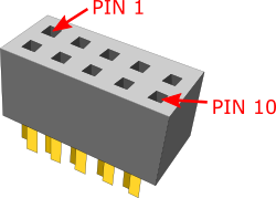 |

The pin 1 position is marked with a small white square on the PCB. Additionally, the pin is marked with a number 1 directly on the debug adapter target connector from revision C1 on.
Jumper J1
The jumper J1 has been put on the debug adapter only for making provision for future extensions of the “ECU14” target connection.
The USERIO signal (target debug connector pin 7) is connected to the BlueBox output (J1 in the position 1-2) or to the BlueBox input (J1 in the position 2-3). Currently the signal has no functionality and consequentially the J1 doesn’t bridged any of the two positions.
Jumper J2
The jumper J2 is optional and by default not bridged. It connects 10k pull-down resistor to the USERIO pin when bridged.
The jumper has been introduced for a custom target, where the target watchdog gets disabled during the debugging, when low level at the USERIO signal (pin 7) is detected.
The debug adapter connects to the target via a 10-pin 1.27mm connector, Samtec SFM-105-01-S-D. A target should feature a matching part, for example Samtec TFM-105-01-L-D.
|
Make sure this adapter fits on your target connector - check Cross Table. |
|
Refer to Hardware Setup and Configuration Tutorial for more information on how to connect the hardware. |