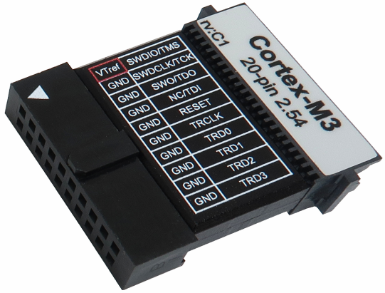
20-pin Cortex (2.54mm) Debug Adapter
This debug adapter is used to connect the iC5000 and the iC5700 BlueBox to the Cortex-M based target. It’s used to connect to the embedded target featuring a 20-pin 2.54 mm pitch target debug connector with the Cortex-M pinout. Its operating voltage range is 3.3V - 5.0V. This particular connector with its pinout is not recommended for new designs and is still available for legacy reasons only.
The debug adapter connects to the 25 cm 40-pin ribbon cable coming from the BlueBox and to the target debug connector on the other side.
Note that the connector has the same physical dimensions as 20-pin 2.54mm Arm Debug Adapter (Ordering code IC50111-1), which is still widely used but the pinouts are completely different. Note that ground signals are on the opposite side, which means using incorrect debug adapter can damage the hardware in worst case.
The following pinout is valid on the target side:
Signal Direction |
Signal Description |
Signal |
Pin |
Pin |
Signal |
Signal Description |
Signal Direction |
|---|---|---|---|---|---|---|---|
I |
Reference Voltage |
Vref |
1 |
2 |
SWDIO/TMS |
SWD/JTAG |
I/O |
|
Ground |
GND |
3 |
4 |
SWCLK/TCK |
SWD/JTAG |
O |
|
Ground |
GND |
5 |
6 |
SWO/TDO |
SWD/JTAG |
I |
|
Ground |
GND |
7 |
8 |
NC/TDI |
Not Connected / JTAG |
O |
|
Ground |
GND |
9 |
10 |
nRESET |
Reset |
I/O |
|
Ground |
GND |
11 |
12 |
TRCLK |
Trace Clock |
I |
|
Ground |
GND |
13 |
14 |
TRD0 |
Trace Data |
I |
|
Ground |
GND |
15 |
16 |
TRD1 |
Trace Data |
I |
|
Ground |
GND |
17 |
18 |
TRD2 |
Trace Data |
I |
|
Ground |
GND |
19 |
20 |
TRD3 |
Trace Data |
I |
20-pin Cortex pinout
Blue colored signals are parallel trace signals.
Signal Direction is described from the BlueBox perspective.
|
When initially connecting the BlueBox to a target, ensure the debug adapter pinout matches the Target connector to avoid potential hardware failure. |
The debug adapter features resettable fuses on pins 1, 2, 4, 6, 8 and 10. These protect debug signals against overcurrent. These fuses cycle back to a conductive state after the excessive current fades away. The debug adapter connects to the target via a 20-pin 2.54 mm connector, for example Yamaichi FAS-2001-2101-2-0BF. A target should feature a matching part, for example WÜRTH ELEKTRONIK: 612 020 216 21.
|
Make sure this adapter fits on your target connector - check Cross Table. |
|
Refer to Hardware Setup and Configuration Tutorial for more information on how to connect the hardware. |

