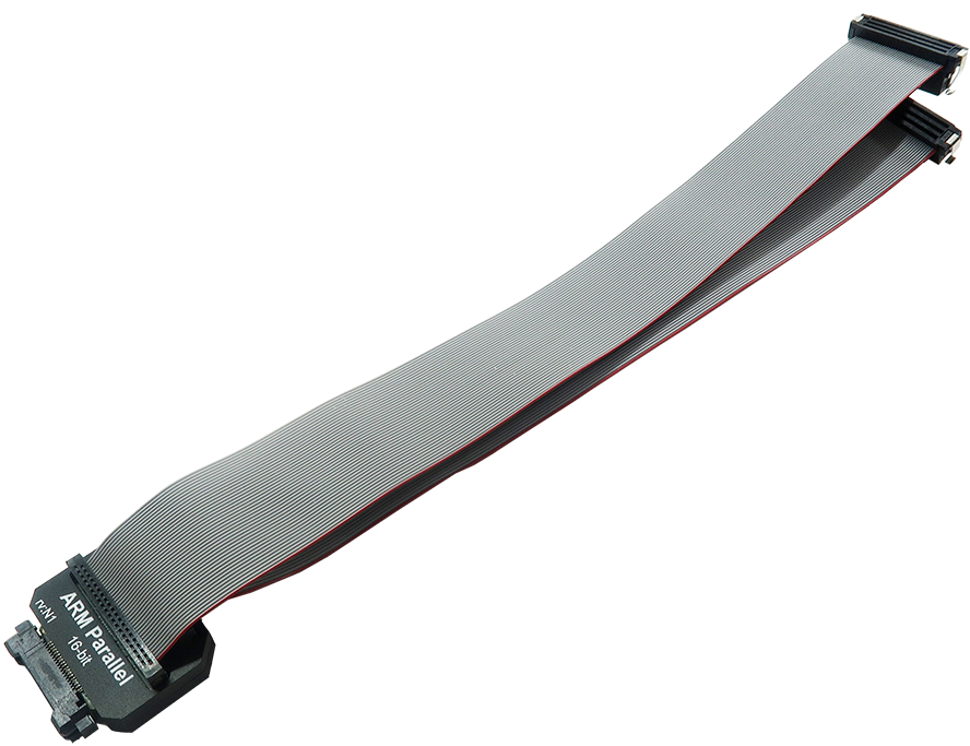
38-pin Mictor Arm Parallel 16-bit Debug Adapter
This debug adapter is used to connect the iC5000 and the iC5700 BlueBox to the Cortex-A, the Cortex-R, the Arm7 and the Arm9 based target. It’s used to connect to the embedded target featuring a 38-pin Mictor target debug connector with the Arm ETMv1 or the Arm ETMv3 pinout. Its operating voltage range is 3.3V - 5.0V. Use 38-pin Mictor Low Voltage Arm Parallel 16-bit Debug Adapter (Ordering code IC50115-LV) for voltages below this range.
The same debug adapter covers the Arm ETMv1 and the Arm ETMv3 pinout.
|
When initially connecting the BlueBox to a target, ensure the debug adapter pinout matches the Target connector to avoid potential hardware failure. |
The debug adapter features resettable fuses on pins 9, 11, 12, 15, 17, 19 and 21. These protect debug signals against overcurrent and cycle back to a conductive state after the excessive current fades away. Signals on pins 6, 16, 18, 20 and 22-38 are protected via 47 ohm serial resistors.
The debug adapter connects to the target via a 38-pin Mictor connector, for example Tyco Electronics 5767055-1. A target should feature a matching part, for example Tyco Electronics 5767081-1 in SMT technology.
|
Only 8- and 16-bit parallel trace width is supported. |
|
Make sure this adapter fits on your target connector - check Cross Table. |
|
Refer to Hardware Setup and Configuration Tutorial for more information on how to connect the hardware. |
The following pinout is valid on the target side for the ARM ETMv1:
Signal Direction |
Signal Description |
Signal |
Pin |
Pin |
Signal |
Signal Description |
Signal Direction |
|---|---|---|---|---|---|---|---|
|
Not Connected |
NC |
1 |
2 |
NC |
Not Connected |
|
|
Not Connected |
NC |
3 |
4 |
NC |
Not Connected |
|
|
Not Connected |
NC |
5 |
6 |
TRACECLK |
Trace Clock |
I |
|
Not Connected |
NC |
7 |
8 |
NC |
Not Connected |
|
O |
Reset |
nRESET |
9 |
10 |
NC |
Not Connected |
|
I |
JTAG |
TDO |
11 |
12 |
Vref |
Reference Voltage |
I |
|
Not Connected |
NC |
13 |
14 |
NC |
Not Connected |
|
O |
JTAG |
TCK |
15 |
16 |
TRACEPKT[7] |
Trace Data |
I |
O |
JTAG |
TMS |
17 |
18 |
TRACEPKT[6] |
Trace Data |
I |
O |
JTAG |
TDI |
19 |
20 |
TRACEPKT[5] |
Trace Data |
I |
O |
JTAG |
nTRST |
21 |
22 |
TRACEPKT[4] |
Trace Data |
I |
I |
Trace Data |
TRACEPKT[15] |
23 |
24 |
TRACEPKT[3] |
Trace Data |
I |
I |
Trace Data |
TRACEPKT[14] |
25 |
26 |
TRACEPKT[2] |
Trace Data |
I |
I |
Trace Data |
TRACEPKT[13] |
27 |
28 |
TRACEPKT[1] |
Trace Data |
I |
I |
Trace Data |
TRACEPKT[12] |
29 |
30 |
TRACEPKT[0] |
Trace Data |
I |
I |
Trace Data |
TRACEPKT[11] |
31 |
32 |
TRACESYNC |
Trace Data |
I |
I |
Trace Data |
TRACEPKT[10] |
33 |
34 |
PIPESTAT[2] |
Trace Data |
I |
I |
Trace Data |
TRACEPKT[9] |
35 |
36 |
PIPESTAT[1] |
Trace Data |
I |
I |
Trace Data |
TRACEPKT[8] |
37 |
38 |
PIPESTAT[0] |
Trace Data |
I |
ETMv1 target pinout
The following pinout is valid on the target side for the ARM ETMv3:
Signal Direction |
Signal Description |
Signal |
Pin |
Pin |
Signal |
Signal Description |
Signal Direction |
|---|---|---|---|---|---|---|---|
|
Not Connected |
NC |
1 |
2 |
NC |
Not Connected |
|
|
Not Connected |
NC |
3 |
4 |
NC |
Not Connected |
|
|
Ground |
GND |
5 |
6 |
TRACECLK |
Trace Clock |
I |
|
Not Connected |
NC |
7 |
8 |
NC |
Not Connected |
|
O |
Reset |
nRESET |
9 |
10 |
NC |
Not Connected |
|
I |
JTAG |
TDO |
11 |
12 |
Vref |
Reference Voltage |
I |
|
Not Connected |
NC |
13 |
14 |
NC |
Not Connected |
|
O |
JTAG |
TCK |
15 |
16 |
TRACEDATA7 |
Trace Data |
I |
O |
JTAG |
TMS |
17 |
18 |
TRACEDATA6 |
Trace Data |
I |
O |
JTAG |
TDI |
19 |
20 |
TRACEDATA5 |
Trace Data |
I |
O |
JTAG |
nTRST |
21 |
22 |
TRACEDATA4 |
Trace Data |
I |
I |
Trace Data |
TRACEDATA15 |
23 |
24 |
TRACEDATA3 |
Trace Data |
I |
I |
Trace Data |
TRACEDATA14 |
25 |
26 |
TRACEDATA2 |
Trace Data |
I |
I |
Trace Data |
TRACEDATA13 |
27 |
28 |
TRACEDATA1 |
Trace Data |
I |
I |
Trace Data |
TRACEDATA12 |
29 |
30 |
GND |
Ground |
I |
I |
Trace Data |
TRACEDATA11 |
31 |
32 |
GND |
Ground |
I |
I |
Trace Data |
TRACEDATA10 |
33 |
34 |
Vref |
Reference Voltage |
I |
I |
Trace Data |
TRACEDATA9 |
35 |
36 |
TRACECTL |
Trace Data |
I |
I |
Trace Data |
TRACEDATA8 |
37 |
38 |
TRACEDATA0 |
Trace Data |
I |
ETMv3 target pinout
Blue colored signals are trace signals.
Signal Direction is described from the BlueBox perspective.

