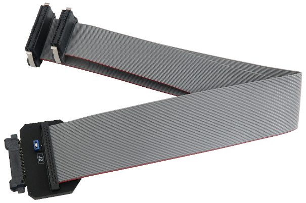
38-pin Mictor MPC5xxx Nexus 16-bit Debug Adapter
This debug adapter is used to connect the BlueBox to NXP MPC5xxx / ST SPC5 based target. It’s used to connect to the embedded target featuring a 38-pin Mictor target debug connector with the MPC5xxx Nexus pinout.
The debug adapter connects to the BlueBox through the two ribbon cables and to the target debug connector on the other side.
The debug adapter features a standard ribbon cable length, which is cca. 24 cm. A debug adapter with shorter cable length, 12 cm, (Ordering code IC50152-12) is used for situations when standard length doesn’t work e.g. due to a badly designed target board layout where reliable Nexus trace capture with the standard 24 cm ribbon cable cannot be achieved.
Jumper J2 (EVTIN)
Under some circumstances it can happen that the debugger cannot find any absolute program counter message in the analyzed Nexus trace stream. Consequently, the program trace reconstruction fails and errors or nothing gets displayed in the trace window. To avoid such situations, the BlueBox can feed periodic signal to the EVTIN CPU pin connecting to the on-chip Nexus trace engine, which then periodically generates and broadcasts program counter synchronization messages.
In order to use this feature, the jumper J2 must be bridged and the Force periodic Nexus SYNC option in the Hardware / CPU Options / Nexus tab must be checked in winIDEA. Refer to winIDEA Help for more details on the Force periodic Nexus SYNC option use.
Note that the EVTI (Nexus Event In) CPU pin may be shared with other CPU functionalities. For instance, on the MPC5516 the same pin can operate as the GPIO, the EBI read/write or the EVTI. Whenever the CPU pin is configured and used for the EVTI alternate operation, the J2 must not be populated in order to prevent electrical conflicts.
|
Typically, there is no need to use the Force periodic Nexus SYNC functionality unless a specific application code is traced, which does not generate messages containing absolute program counter information. As long as the user has no problems with the trace use, it is recommended to keep the jumper J2 disconnected. |
|
Jumper J2 was introduced with the debug adapter revision N1. Earlier versions don’t provide this jumper. |
The following pinout is valid on the target side:
Signal Direction |
Signal Description |
Signal |
Pin |
Pin |
Signal |
Signal Description |
Signal Direction |
|---|---|---|---|---|---|---|---|
I |
Message Data Outputs |
MDO[12] |
1 |
2 |
MDO[13] |
Message Data Outputs |
I |
I |
Message Data Outputs |
MDO[14 |
3 |
4 |
MDO[15] |
Message Data Outputs |
I |
I |
Message Data Outputs |
MDO[9] |
5 |
6 |
NC |
Not Connected |
|
|
Not Connected |
NC |
7 |
8 |
MDO[8] |
Message Data Outputs |
I |
I/O |
Reset |
nRESET |
9 |
10 |
EVTIN |
Nexus Event Input |
O |
I |
JTAG |
TDO |
11 |
12 |
Vref |
Reference Voltage |
I |
I |
Message Data Outputs |
MDO[10] |
13 |
14 |
NC |
Not Connected |
I |
O |
JTAG |
TCK |
15 |
16 |
MDO[7] |
Message Data Outputs |
I |
O |
JTAG |
TMS |
17 |
18 |
MDO[6] |
Message Data Outputs |
I |
O |
JTAG |
TDI |
19 |
20 |
MDO[5] |
Message Data Outputs |
I |
O |
JTAG TRST (optional) |
nJCOMP |
21 |
22 |
MDO[4] |
Message Data Outputs |
I |
I |
Message Data Outputs |
MDO[11] |
23 |
24 |
MDO[3] |
Message Data Outputs |
I |
|
Not Connected |
NC |
25 |
26 |
MDO[2] |
Message Data Outputs |
I |
|
Not Connected |
NC |
27 |
28 |
MDO[1] |
Message Data Outputs |
I |
|
Not Connected |
NC |
29 |
30 |
MDO[0] |
Message Data Outputs |
I |
|
Not Connected |
NC |
31 |
32 |
EVTO |
Nexus Event Output |
I |
|
Not Connected |
NC |
33 |
34 |
MCKO |
Message Data Clock |
I |
|
Not Connected |
NC |
35 |
36 |
MSEO[1] |
Message Data Clock |
I |
|
Not Connected |
NC |
37 |
38 |
MSEO[0] |
Message Data Clock |
I |
38-pin MPC5xxx and SPC56 16-bit Nexus target pinout
Signal Direction is described from the BlueBox perspective.
Debug adapter features resettable fuses on pins 9, 10, 11, 12, 15, 17, 19 and 21. These protect debug signals against overcurrent and cycle back to a conductive state after the excessive current fades away. Signals on pins 1, 2, 3, 4, 5, 8, 13, 14, 16, 18, 20, 22, 23, 24, 26, 28, 30, 32, 34, 36 and 38 are protected via 47 ohm serial resistors.
The debug adapter connects to the target via a 38-pin Mictor connector, Tyco Electronics 5767055-1. A target should feature a matching part, for example Tyco Electronics 5767081-1 in the SMT technology.
|
Make sure this adapter fits on your target connector - check Cross Table. |
|
Refer to Hardware Setup and Configuration Tutorial for more information on how to connect the hardware. |

