Device description
|
|
|
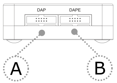
A – 10-pin DAP connector, with the following pinout:
Signal Direction |
Signal Description |
Signal |
Pin |
Pin |
Signal |
Signal Description |
Signal Direction |
|---|---|---|---|---|---|---|---|
I |
Reference Voltage |
Vref |
1 |
2 |
DAP1 |
DAP Data |
I/O |
|
Ground |
GND |
3 |
4 |
DAP0 |
DAP Clock |
O |
|
Ground |
GND |
5 |
6 |
DAP2 |
Optional 2nd Data Pin |
I/O |
|
Not Connected |
NC |
7 |
8 |
nTRST/DAPEN |
Optional 3rd Data Pin |
I/O |
|
Ground |
GND |
9 |
10 |
nRESET |
Reset |
O |
10-pin DAP pinout
B – 10-pin DAPE connector, with the following pinout:
Signal Direction |
Signal Description |
Signal |
Pin |
Pin |
Signal |
Signal Description |
Signal Direction |
|---|---|---|---|---|---|---|---|
I |
Reference Voltage |
Vref |
1 |
2 |
DAPE1 |
DAP Data |
I/O |
|
Ground |
GND |
3 |
4 |
DAPE0 |
DAP Clock |
O |
|
Ground |
GND |
5 |
6 |
DAPE2 |
Optional 2nd Data Pin |
I/O |
|
Not Connected |
NC |
7 |
8 |
DAPEN/DAP3 |
Optional 3rd Data Pin |
I/O |
|
Ground |
GND |
9 |
10 |
NC |
Not Connected |
|
10-pin DAPE pinout
Signal direction definition:
O – Output from the Active Probe to the target microcontroller
I – Input to the Active Probe from the target microcontroller
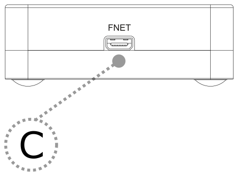
C – FNet Micro connector, that connects the Active Probe to the iC5700 BlueBox. The FNet Micro cable is delivered with the Active Probe.
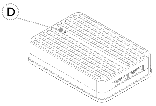
D – The indicator light provides the status of the Active Probe as follows:
|
Permanently green – Powered on and ready to use. |
|
Blinking green – Establishing connection with the BlueBox. |
|
Blinking blue – Reprogramming SPLASH. |
|
Permanently magenta – Golden image loaded and ready to use. |


|
When powering on the system, switch the iC5700 on before powering on the target system. When powering down the system, power off the target before powering off the iC5700! Use only original TASKING accessories for powering and connecting with the iC5700. Consult with TASKING before attempting to use any other accessory. |
