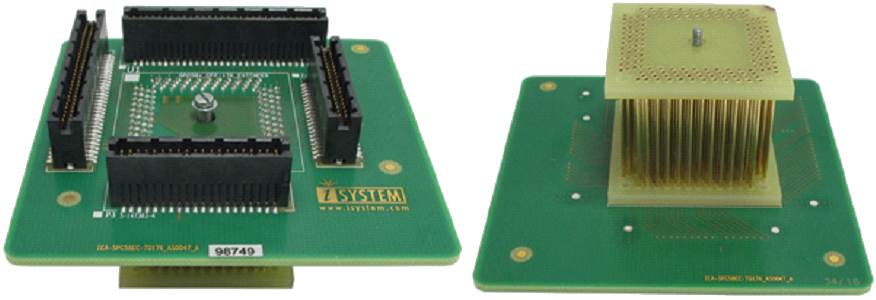
QFP Fixed Assembly
|
Watch out that the pin 1 position and alignment of all pins. Avoid disassembling and reassembling the hardware setup too frequently. |
1. Solder the Solder part [B] on the target PCB [A] to get a BA setup.
|
Use the Surface Mount Technology (SMT) to solder the Solder parts to the target instead of the original microcontroller. We provide this soldering service on request. |
2. Assemble the in order: Emulation Adapter [E], optional Measurement board [D], the Conversion board [C], together to get an E(D)C setup.
3. Assemble the E(D)C setup with the BA setup by connecting the Conversion board of the E(D)C setup to the Solder part of the BA setup.
Slot screw
The Slot screw (30mm) is used to fix the Conversion board to the Solder part. The setup becomes mechanically more robust. Screw the Conversion board to the Solder part first, before the Emulation Adapter is attached on top and watch out not to break out the Solder part, e.g., if you accidentally hit the Emulation Adapter from the side.


