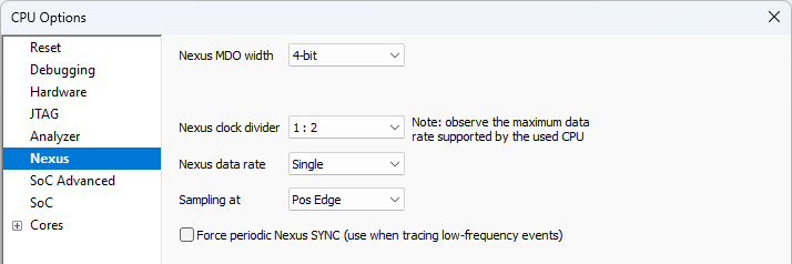
Nexus
Nexus Port is selected in the Hardware | CPU Options | Analyzer page | Operation mode section.
|
This page is available only when debugging is performed via iC5000 BlueBox system. Only configuration options which are relevant to the selected CPU and platform are displayed. |

Nexus MDO width
Nexus signals can be located on the alternate CPU pins, which can be configured for different alternate functions.
MPC5500 devices
The MPC5500 devices allow configuring Nexus MDO port either as 4 or 12-bit port. A 12-bit MDO implementation ensures optimum Nexus operation. A 4-bit MDO implementation requires less CPU signals than the 12-bit MDO but the Nexus throughput is decreased, which is a crucial factor for correct trace operation. Note that the trace displays errors when the CPU doesn’t manage to send out complete Nexus messages to the external development system. It’s highly probably that 4-bit MDO port will result in trace errors while 12-bit MDO port will function flawlessly.
MPC551x devices
MPC551x device can have either 4-bit or 8-bit Nexus MDO port and MPC56xx devices can have either 2-bit or 4-bit Nexus MDO port.
The debugger displays available Nexus MDO width based on selected CPU. See also overview table on page 2 for available MDO width for different microcontrollers.
In general the user should opt for wider Nexus port since it provides maximum bandwidth of the Nexus interface. When the target implements only the lower Nexus MDO count of the two possible, the system will be more prone to Nexus overflows.
Nexus clock divider
This selection directly affects Nexus clock.
1:1 selection yields maximum Nexus clock. However, typically when the CPU clock goes over 100MHz, 1:2 selection must be used in order to reduce the Nexus clock frequency. Note that Nexus signals are typically located on CPU I/O pins as an alternate operation. Output drivers of the I/O ports are typically designed for frequencies below 100MHz, which means they are not capable of driving Nexus signals at e.g. 128MHz. For this reason, Nexus clock is controlled over the Nexus clock divider in order not to exceed the maximum frequency of the physical Nexus ports.
For example, let’s take a look MPC5643L device. As long as the CPU runs at 64MHz, 1:1 Nexus clock divider will work. When the same CPU runs at 128MHz, 1:2 Nexus clock divider must be used. However, this also halves the Nexus port bandwidth that is the amount of information which can be broadcasted over the Nexus port. Nexus overflows will occur when the nexus port bandwidth is exceeded.
Therefore, per default the divider should be 1:1 and it should be set to1:2 only when otherwise Nexus clock would exceed the maximum frequency of the Nexus port.
|
Refer to the CPU’s Reference Manual / AC Specifications / PAD AC Specifications for maximum port frequency of a particular device. |
Nexus data rate
On some fast CPUs, it is possible to configure CPU to broadcast Nexus messages at double data rate (at every clock edge), which yields double Nexus port bandwidth. This means the Nexus trace will less likely overflow, which happens when the Nexus traffic is higher than the Nexus port bandwidth.
Sampling at
Per default, Nexus signals are sampled at positive edge of the Nexus clock. However, some targets may have delayed Nexus data signals comparing to the Nexus clock to such extent that it might be necessary to sample data on negative edge of the Nexus clock in order to capture valid Nexus information.
Force periodic Nexus SYNC
When there are problems with the trace or profiler (for instance no content is displayed), it is recommended to check this option for test. If the application runs in some loop, which generates no SYNC nexus messages it may happen that the trace decoder cannot reconstruct any absolute CPU address from the recorded Nexus messages. When this option is checked, the debugger periodically inserts extra Nexus SYNC messages, which allow the trace and the profiler to reconstruct absolute CPU address for every such message.
