Reset
This chapter explains setup for reset in initialization operation. Open Hardware | CPU Options | Reset.
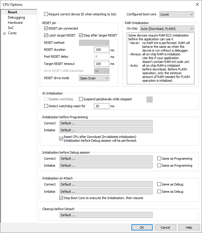
Configured boot core
Selected the boot core according to your application design.
|
Note that this option does not change the boot core on SoC, but only informs winIDEA about which core is being used as a boot core. |
RESET pin connected
Disable this option when the target reset line is not connected to the debug connector.
Latch target RESET
System reset line drivers on debugger side and target side are open collector. Either can pull it low. Assertion from target side can be missed by debugger if it is shorter than poll period of reset line. When the option is checked (default) the debugger hardware latches the reset line when being pulled low by target system. When polled next time the winIDEA acknowledges reset state. This yields a delay from when line is asserted by the target reset and the acknowledgement by winIDEA and potential restart of application. An example is an application where the CPU is periodically set into a power save mode and then woken up by an external reset circuit. In such case a delay introduced by the debugger would yield application not operating properly.
When the target voltage falls below 3 V, the MCU is in reset. However, the reset line is not pulled down, so such reset could be undetected by winIDEA until the reset line falls below logical one, which may take up to 10 seconds. In order to quickly detect such a reset, the Vref line is regularly polled, and when it falls below 3 V, winIDEA shows that the target is in reset. This functionality is only available when the Latch target RESET option is enabled. Polling Vref is executed during the idle cycles in the debugger, and since it takes up to 10 ms to perform a poll, it may affect other functions that are performed during the idle cycles of the debugger, such as data acquisition (DAQ).
Stop after target RESET
CPU can be optionally stopped after the CPU reset is detected and handled. If the option is unchecked, the application is resumed upon reset release.
Driving the SRST signal
The diagram below shows how the SRST line is driven when a reset is applied. Depending on your hardware, it is possible to adjust the timings to your need.

RESET Duration
Specify the length of the pulse on the SRST line.
Post RESET Delay
Specify the delay that winIDEA will wait after releasing the SRST line, before it tries to connect to the on-chip debug module and establish the debug session.
Once the SRST is released, the on-chip debug module may need some time to become operational. This time can also depend on any additional reset circuitry on the target system. Keep in mind that the longer this delay, more of the code will be executed before the CPU is stopped or reset, so you should keep this setting as low as possible, while still giving the system time to stabilize.
Target RESET timeout
Specify the timeout that winIDEA will wait after releasing the SRST line, before it detects a high value. This timeout should be configured for targets that have a weak pull-up on the SRST line.
Drive RESET while Detached:
•no - BlueBox will not drive the RESET line. RESET will or will not occur depending on your application design.
•Low - BlueBox will pull down the RESET line. RESET will most likely not occur.
•High - BlueBox will pull up the RESET line. RESET will most likely occur.
Make sure that this option is set to Low. Other possibilities let the RESET line go high and a flash programmed application will run for about 40ms before a debug mode sequence is started by the debugger. Application runaway can cause problems with debugger connecting to the MCU debug unit.
RESET drive mode:
•Open-drain + Pull-up - RESET pin is configured as an open-drain output with pull-up. This is the preferred configuration. winIDEA can also detect when the external circuit on the target activates the RESET pin.
•Push-pull - RESET pin is configured as a push-pull output. Should be used with caution. The external circuit on the target must not actively drive the RESET pin, otherwise the debug adapter might get bricked.
•No drive - RESET pin will not be driven, except for the fixed internal pull-up resistor. The pin is configured as read-only, so external RESET requests will be detected. The Latch target RESET functionality is not changed.
•Open-drain - RESET pin is configured as an open-drain output without pull-up. winIDEA can also detect when the external circuit on the target activates the RESET pin. Pull-up on the RESET line should be implemented on the target.
Not all RESET drive modes are available in all configurations. For example, the No drive mode is not supported by iC5000.
At Initialization
Suspend peripherals while stopped
When this option is checked, selected peripheral functions (e.g., timers) are stopped when the application is stopped. Peripheral functions can be selected via the button  . It is generally recommended that this option is checked, as this results in more predictable behavior of the debugged application when using these peripheral functions.
Refer to the microcontroller and architecture reference manuals for details.
|
This option, including its peripherals list, is available for specific microcontrollers only. If not supported, the option is greyed out. |
Initialization
Primarily, initialization sequence is used on On-Chip Debug systems to initialize the CPU after reset to be able to download the code to the target (CPU or CPU external) memory.
Typically, there is no need to use the initialization sequence in case of the RL78. Initialization sequence may be required on some CPU families when it is required by the application being debugged. The debugger executes initialization immediately after reset and then downloads the code. Detailed information may be found in the Initialization Sequence help topic.
|
Hot Attach function cannot be used for any flash programming or code download! |
