Trace Port
Trace Port is comprised of several dedicated CPU pins, through which the trace messages can be streamed. These signals are typically routed to the debug connector, through which the iSYSTEM tools communicate with the CPU and record the trace messages when they are being streamed. Once the trace message is recorded, iSYSTEM tools append a timestamp and therefore provide the timing information.
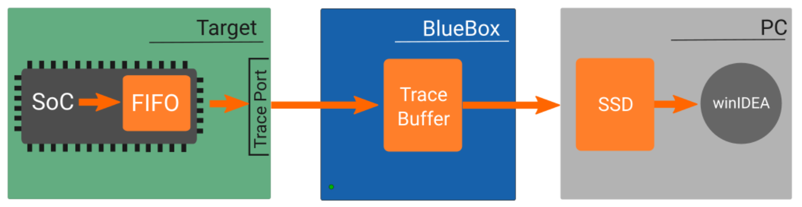
There are some inevitable drawbacks compared to the On-Chip Trace Buffer (OCTB):
FIFO overflow
Since the CPU activity is compressed and qualifier is employed, trace messages are not generated at a constant rate. While the trace port is sized to sustain an average bandwidth, at times the rate of generated messages will exceed it.
To compensate, the OCT module uses a message FIFO (typically 16-64 entries deep). Still, if the qualifier is set too widely, FIFO can get filled and subsequent OCT messages cannot be inserted.
Such situation can be handled in these manners:
•Trace is stopped, indicating FIFO overflow.
•Trace messages (usually the data trace) are suppressed until FIFO is freed to some level, then they resume, creating a gap.
•CPU is stalled until one FIFO entry is free.
FIFO overflows can be avoided by limiting the amount of information you wish to record or by increasing the trace port bandwidth (either by using a wider port or a higher trace clock).
Timestamp accuracy
Timestamp is generated by the BlueBox, when a trace message is received and stored in the buffer. However, message propagation delay from the observed event to the trace port output is not constant – because one message might stream immediately, but another would have to wait multiple cycles in the FIFO. While this reduces the time accuracy considerably, it is in practice less noticeable because:
•FIFO load is relatively constant - and usually low, if sustained traces are required.
•If program trace is recorded, the tool can (in the analysis stage) interpolate the time based on executed op-codes and thus compensate for deviations.
Note for hardware designers
If you are designing the hardware which will include a trace port, please refer to the PCB Design Guidelines, which explain how the hardware should be designed to for optimal trace signal integrity.