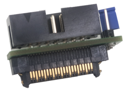
14-pin 2.54mm RH850 to RH850 Aurora 46-pin Converter
The following pinout is available on the target side:
Signal Direction |
Signal Description |
Signal |
Pin |
Pin |
Signal |
Signal Description |
Signal Direction |
|
Not Connected |
NC |
1 |
2 |
Vref |
Reference Voltage |
I |
|
Not Connected |
NC |
3 |
4 |
LPDCLK/TCK |
Debug Clock |
O |
|
Ground |
GND |
5 |
6 |
NC |
Not Connected |
|
|
Not Connected |
NC |
7 |
8 |
NC |
Not Connected |
|
|
Not Connected |
NC |
9 |
10 |
NC |
Not Connected |
|
|
Ground |
GND |
11 |
12 |
nTRST |
JTAG |
O |
|
Not Connected |
NC |
13 |
14 |
FLMD0 |
Flash Mode |
O |
|
Not Connected |
NC |
15 |
16 |
NC |
Not Connected |
|
|
Ground |
GND |
17 |
18 |
NC |
Not Connected |
|
|
Not Connected |
NC |
19 |
20 |
NC |
Not Connected |
|
|
Not Connected |
NC |
21 |
22 |
nRESET |
Reset |
I/O |
|
Ground |
GND |
23 |
24 |
GND |
Ground |
|
|
Not Connected |
NC |
25 |
26 |
NC |
Not Connected |
|
|
Not Connected |
NC |
27 |
28 |
NC |
Not Connected |
|
|
Ground |
GND |
29 |
30 |
GND |
Ground |
|
|
Not Connected |
NC |
31 |
32 |
WDGDIS |
Watchdog disable |
|
|
Not Connected |
NC |
33 |
34 |
NC |
Not Connected |
|
|
Ground |
GND |
35 |
36 |
GND |
Ground |
|
|
Not Connected |
NC |
37 |
38 |
TMS |
JTAG |
O |
|
Not Connected |
NC |
39 |
40 |
LPDI/TDI |
Debug Signal |
O |
|
Ground |
GND |
41 |
42 |
GND |
Ground |
|
|
Not Connected |
NC |
43 |
44 |
LPDO/TDO |
Trace / Debug Signal |
I |
|
Not Connected |
NC |
45 |
46 |
LPDCLKOUT |
Trace Clock / Debug Clock / Synchronization |
I |
46-pin RH850 Aurora target pinout
Signal Direction is described from the BlueBox perspective.
Jumper
Target debug connector provides a watchdog disable signal. A target can implement watchdog disable function through this pin for more predictable debugging of the target application. Sometimes it’s even impossible to debug the target application without disabling the embedded target watchdog logic. When the BlueBox debugger connects to the CPU through the target debug connector, it forces low or high (depending on the J1 setting) level to the watchdog disable signal, which then yields disabling watchdog logic in the target (when supported by the target).
A jumper is present on the adapter which connects high level (Vref voltage) or low level (GND). Jumper position 1 is marked with a white line.
Jumper position 2 (Default): Not connected
Jumper position 1-2: VREF – WDGDIS
Jumper position 2-3: WDGDIS – GND
|
Make sure this adapter fits on your target connector - check Cross Table. |
|
Refer to Hardware Setup and Configuration Tutorial for more information on how to connect the hardware. |
