Mechanical information
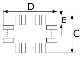
 Solder part solder pad view |
|
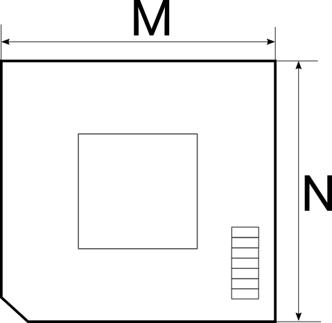
 Top view of the Conversion board |
|
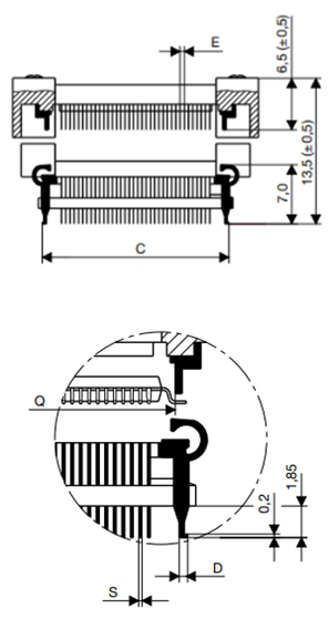
Solder parts
In the case of soldering the Solder part manually, it’s highly recommended to prolong the solder pad E on the outer side (e.g., for 1.5–2 mm) during the PCB design. Note that without this modification, it’s very difficult to solder the Solder part manually.
Recommended PCB footprint dimensions:
Ordering code |
Unit (mm) |
||||||
|---|---|---|---|---|---|---|---|
A |
B |
C |
D |
E |
K |
L |
|
IA64ATQ-SOLDER |
12 |
1.505 |
13.0 |
13.0 |
2.3 |
14 |
14 |
IA80ATQ-SOLDER |
14 |
1.505 |
15.0 |
15.0 |
2.3 |
16.0 |
16 |
IA100TQ-SOLDER |
16.5 |
1.125 |
17.0 |
17.0 |
2.15 |
19.55 |
19.55 |
IA144TQ-SOLDER |
22 |
1.125 |
23.0 |
23.0 |
2.15 |
25.05 |
25.05 |
|
Use the Surface Mount Technology (SMT) to solder the Solder parts to the user target board instead of the original microcontroller. iSYSTEM provides this soldering service on request too. |
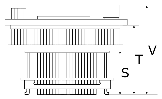
Emulation Adapter
Ordering code |
Unit (mm) |
||||||
|---|---|---|---|---|---|---|---|
M |
N |
P |
R |
S |
T |
V |
|
IEA-CYT2B9 |
70 |
70 |
|
|
32.6 |
38 |
47.5 |
IEA-CYT2B9-xxxx |
|
|
70 |
70 |
|
|
|
|
To view Emulation Adapter schematics, refer to Schematics . |


