Power supply package
Use the enclosed IEA-PS Emulation Adapter Power converter and adapter. A Power supply package, which is delivered with the Emulation Adapter, is required when:
•The Emulation Adapter is used as a standalone device.
•The target board doesn’t provide an accurate supply voltage.
•The target board doesn’t provide sufficient current for the Emulation Adapter operation.
The Power converter can supply either 3.3 V or 5 V. The array of jumpers J0–J9 selects 3.3 V or 5 V voltage on the P3 connector, which connects to the Emulation Adapter.
Signal |
Pin |
Pin |
Signal |
|---|---|---|---|
NC |
1 |
2 |
J0 |
NC |
3 |
4 |
J1 |
NC |
5 |
6 |
J2 |
NC |
7 |
8 |
J3 |
NC |
9 |
10 |
J4 |
NC |
11 |
12 |
J5 |
NC |
13 |
14 |
J6 |
NC |
15 |
16 |
J7 |
NC |
17 |
18 |
J8 |
NC |
19 |
20 |
J9 |
GND |
21 |
22 |
GND |
GND |
23 |
24 |
GND |
GND |
25 |
26 |
KEY |
P3 connector and J0–J9 jumper correlation table
For example, when J2 is in the 3V3 position, it supplies 3.3 V to pin 6 of the P3 connector. When J2 is in the 5V position, it supplies 5 V to pin 6 of the P3 connector pin.
|
Be careful not to supply 5 V to the microcontroller power supply pin, which has declared a maximum voltage 3.3 V! Refer to the microcontroller documentation for detailed information on power supply. |

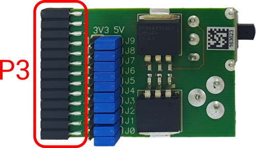
P3 connector on the Power Supply board
External power supply requirements:
Min Voltage |
Max Voltage |
Min Power |
|
|---|---|---|---|
8 V |
12 V |
5 W |