Device description
|
|
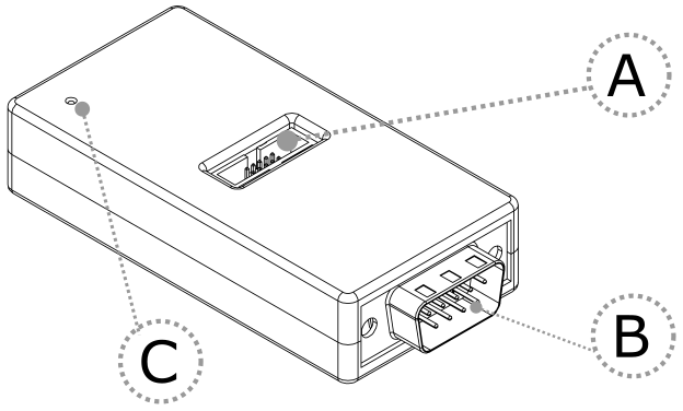
A – DAP connector
Pinout valid on the DAP connector side:
Signal Description |
Signal Direction |
Signal |
Pin |
Pin |
Signal |
Signal Direction |
Signal Description |
|---|---|---|---|---|---|---|---|
Reference voltage |
O |
Vref |
1 |
2 |
TXD |
I |
Transmitter |
Ground |
|
GND |
3 |
4 |
NC |
|
Not Connected |
Ground |
|
GND |
5 |
6 |
RXD |
O |
Receiver |
Not Connected |
|
NC |
7 |
8 |
NC |
|
Not Connected |
Ground |
|
GND |
9 |
10 |
NC |
|
Not Connected |
DAP connector pinout
Signal Direction is described from the BlueBox perspective.
B – DB9 connector
Pinout valid on the DB9 connector side:
Pin |
Signal |
|---|---|
1 |
Not Connected |
2 |
CAN_L |
3 |
CAN GND |
4 |
NC |
5 |
SHIELD |
6 |
NC |
7 |
CAN_H |
8 |
NC |
9 |
NC |
DB9 connector pinout
C – The LED indicator provides the status of the hardware as follows:
•Green – Powered on
•Red – Power supply issue (e.g., burnt fuse)
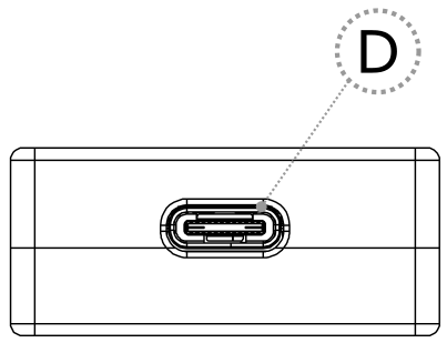
D – Power supply connection for the Converter. Use provided USB-C cable to power the converter e.g. from a PC.
|
CAN 120 Ohm terminating resistor is not implemented on the DAP over CAN Physical Layer Converter. |

|
TASKING provides cable solutions on request with build in terminating resistor, which can be easily switched on or off. |