Device description
iC5700
iC5700 with Hub (optional)
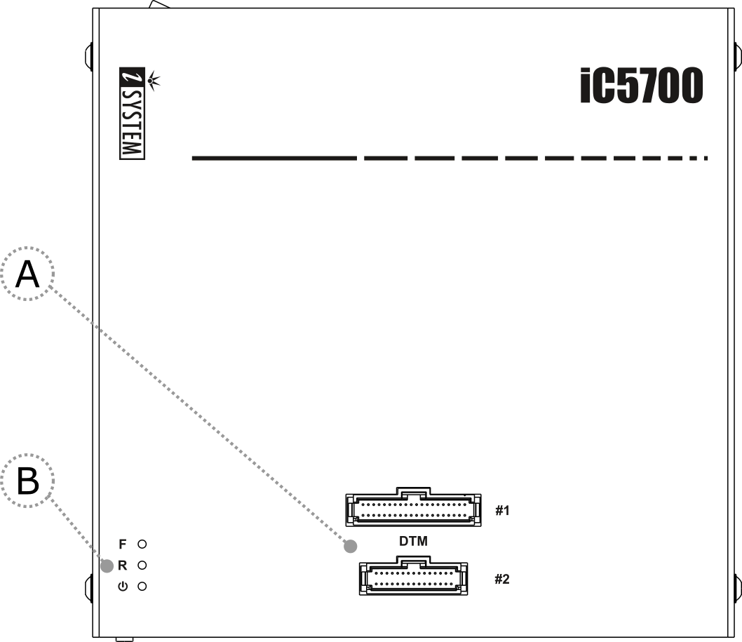
A – Two connectors, marked #1 and #2. These connectors are the interface to the target microcontroller. Depending on the target microcontroller debug features, the supplied ribbon-cables will need to be connected to either connector #1 only or connectors #1 and #2.
B – The indicator lights provide the status of the hardware:
|
Power Indicator |
•On – Powered on
•Off – Powered off
|
R – Running Indicator |
•On – Target microcontroller is executing code
•Off – Target microcontroller is halted
|
F –Free Indicator |
•On – BlueBox is available for a connection from a host PC
•Off – Active connection to the BlueBox from a host PC exists
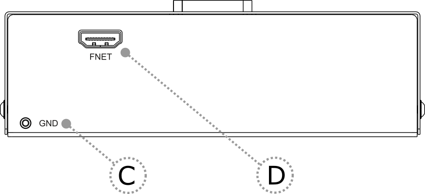
C – The grounding socket (GND) is used together with the Grounding wire to create an electrical connection between the BlueBox and the target circuitry. The socket is suitable for a 2 mm Multi Contact Plug (Banana Plug) if building a longer or a replacement cable on your own.
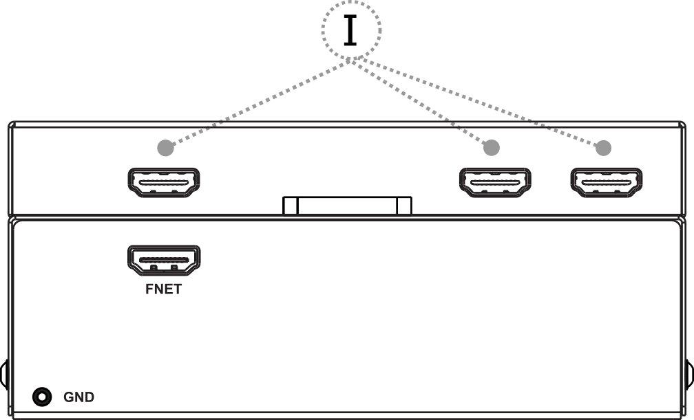
D – The FNet Port provides an interface for the TASKING’s range of ADIO & CAN/LIN Accessories.
|
FNet Port is not compatible with HDMI or any HDMI accessories. Connecting the hardware to the HDMI devices will damage the hardware and will render the hardware warranty void. |
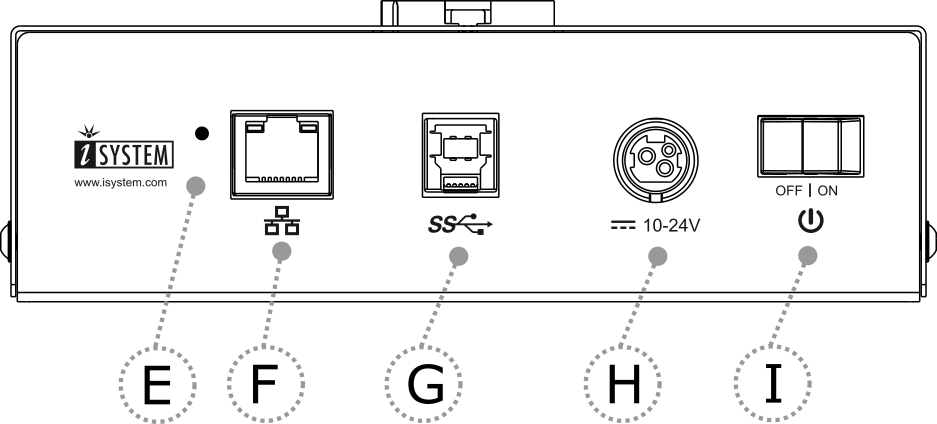
E – Reset (from revision R13). The Reset button loads the default firmware.
|
Use only if advised by the Technical support. |
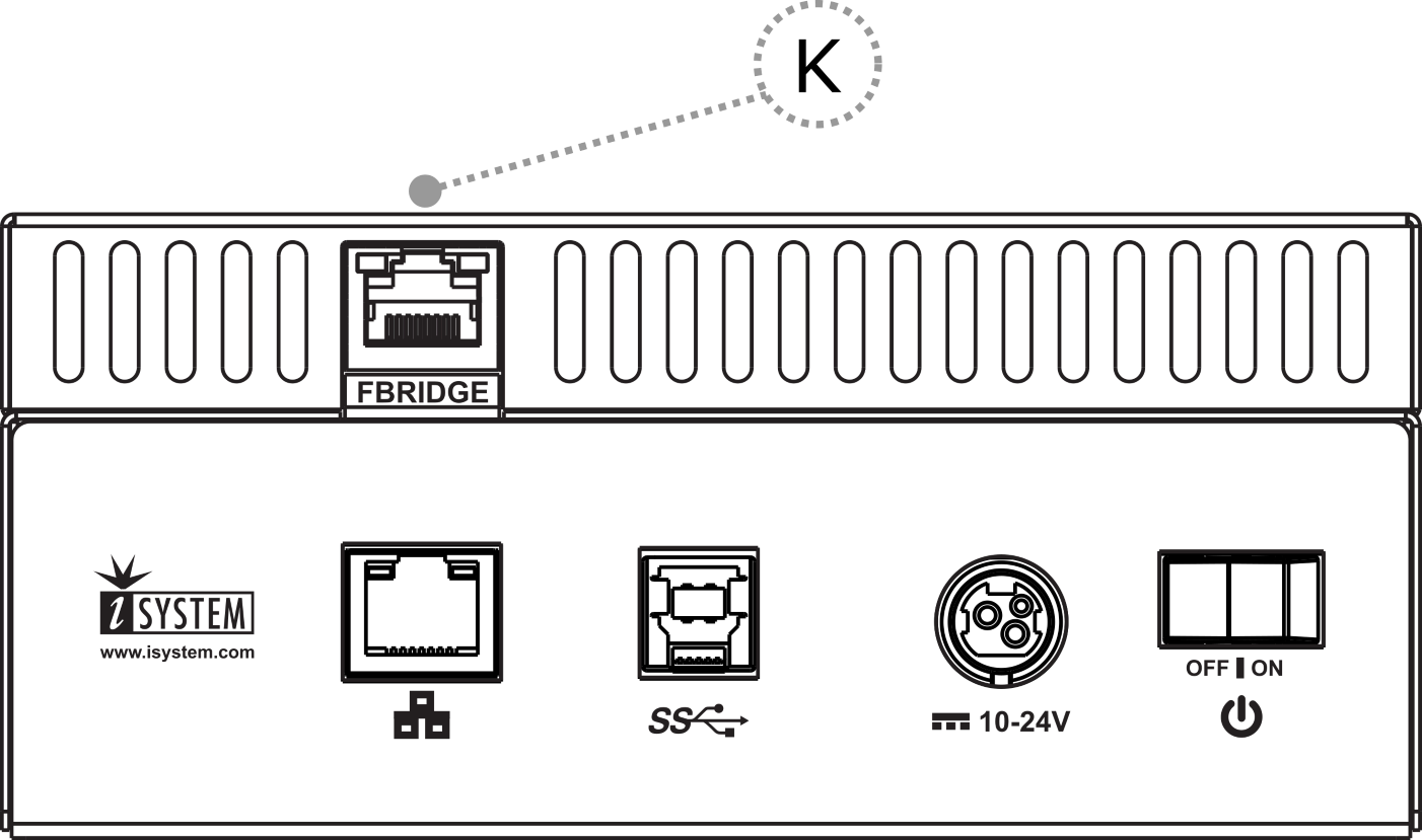
F – 10/100 Ethernet Socket
|
I – Power Switch
|
|
H – Power Supply Socket The socket and plug are latching to stop the plug from being accidentally pulled out of the socket. To remove the power plug from the socket, always pull gently of the sleeve of the plug and never on the wire. |
G – USB 3.0 Socket It is highly recommended to use the USB 3.0 cable, because it fulfills the maximum USB 3.0 transfer rate (5Gbit/s). Use of alternate cables must be undertaken at your own risk. |

Both the 10/100 Ethernet Socket (E) and the USB 3.0 Socket (F) can be connected to a network/PC simultaneously. The active interface will be determined by whichever interface winIDEA connects to first.
|
When powering on the system, switch the BlueBox unit on before powering on the Target. When powering down the system, power off the Target before powering off the BlueBox unit! FBridge port is not Ethernet port! Use only original accessories for powering and connecting with the BlueBox unit. Consult with Technical support before attempting to use any other accessory. |
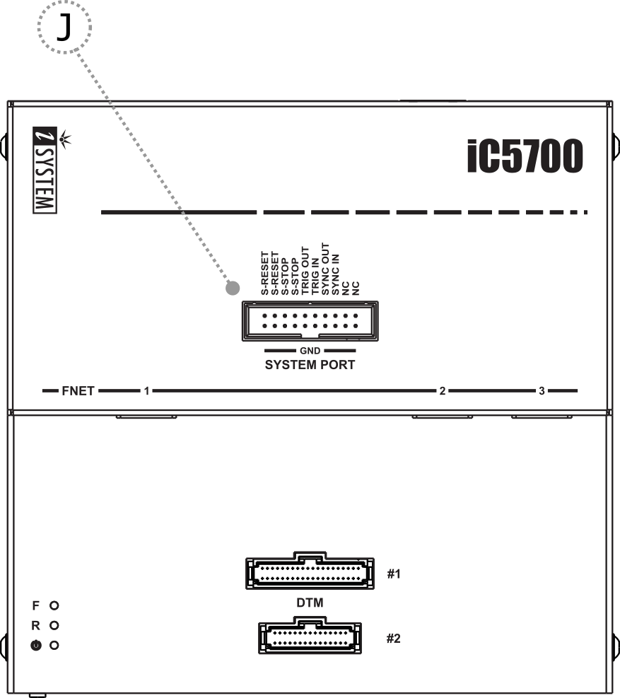
iC5700 with Hub (optional):
I – Three additional FNet ports
J – System port
K – FBridge port (not Ethernet port!) provides synchronization between two iC5700 units
The Hub extends iC5700 with additional three FNet ports and one FBridge port. Through the FBridge port run/stop control of two iC5700 can be synchronized. 1m long FBridge (Ethernet alike) cable comes along the Hub and connects to the FBridge port on each iC5700.
|
If you ordered the Hub to extend the operation, please refer to the Hub installation guide that came with your Hub package. |
