Mechanical information
 Side view of the Solder part |
 Solder part solder pad view |
 Top view of the Solder part |
|
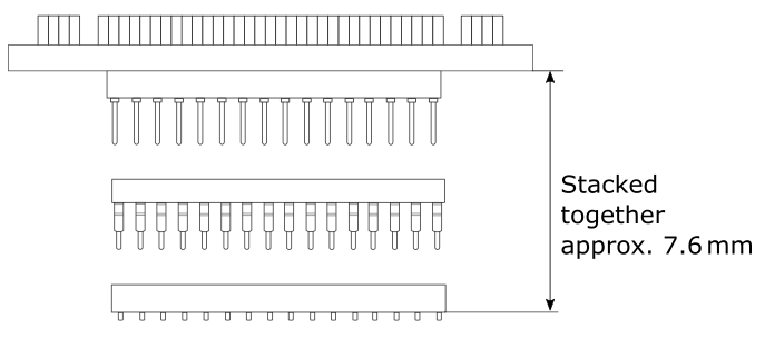
 Side view of the Emulation adapter complete setup - QFP Fixed Adaptation |
|
 Top view of the Emulation Adapter |
 Top view of the Conversion board |
Solder parts
In the case of soldering the Solder part manually, it’s highly recommended to prolong the solder pad E on the outer side (e.g., for 1.5–2 mm) during the PCB design. Note that without this modification, it’s very difficult to solder the Solder part manually.
Recommended PCB footprint dimensions:
Ordering code |
Unit (mm) |
||||||
|---|---|---|---|---|---|---|---|
A |
B |
C |
D |
E |
K |
L |
|
IA176TQ-SOLDER |
26 |
1.125 |
27.0 |
27.0 |
1.9 |
29.05 |
29.05 |
IA144TQ-SOLDER |
22 |
1.125 |
23 |
23 |
2.15 |
25.05 |
25.05 |
BGA302 Adaptation
|
For ordering the correct amount of Extenders go to the ST SPC58 H Adaptations chapter. |
|
|
Side view of the Emulation Adapter, one Extender and Solder part (each Extender adds approx. 3,25mm) |
Top view of the Solder part / Extender |
|
Use the Surface Mount Technology (SMT) to solder the Solder parts to the user target board instead of the original microcontroller. iSYSTEM provides this soldering service on request too. |

Emulation Adapter
Ordering code |
Unit (mm) |
||||||
|---|---|---|---|---|---|---|---|
M |
N |
P |
R |
S |
T |
V |
|
IEA-SPC58NH |
70 |
70 |
|
|
32.6 |
36.4 |
47.5 |
IEA-SPC58NH-xxxxxx |
|
|
70 |
70 |
|
|
|