Schematics
|
To view Emulation Adapter schematics, refer to Schematics . |
Below is a pinout of the four connectors P3-P6 on the bottom side of the emulation adapter:
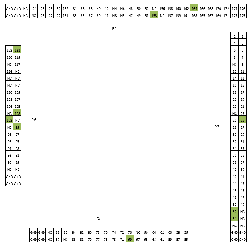
NC – Not Connected
Green marked squares – Voltage pins
Optionally, the user could also design his target directly providing connection for the emulation adapter via the P3-P6 connectors. Connectors being used on the emulation adapter side are TE connectivity female connectors, part number: 0-0104652-4 (40-pin connector) and 0-0104652-6 (60-pin connector). The target must feature male matching connectors.