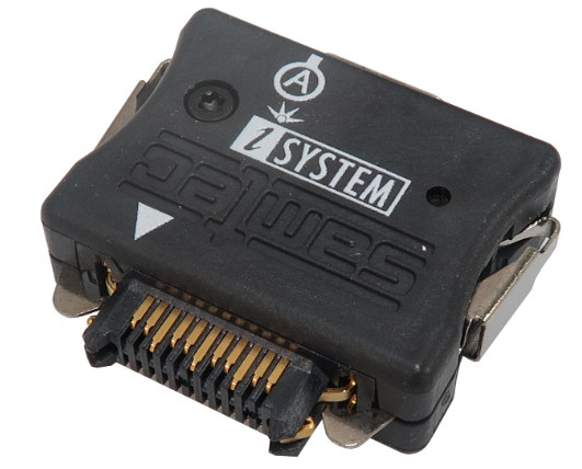
HSTCU (USB-C) to Samtec22 Converter
The converter is used to connect the Infineon SGBT (HSTCU) Active Probe with the USB-C connector to a target featuring Samtec 22-pin ERF8 debug connector. The 22-pin converter must be ordered separately.
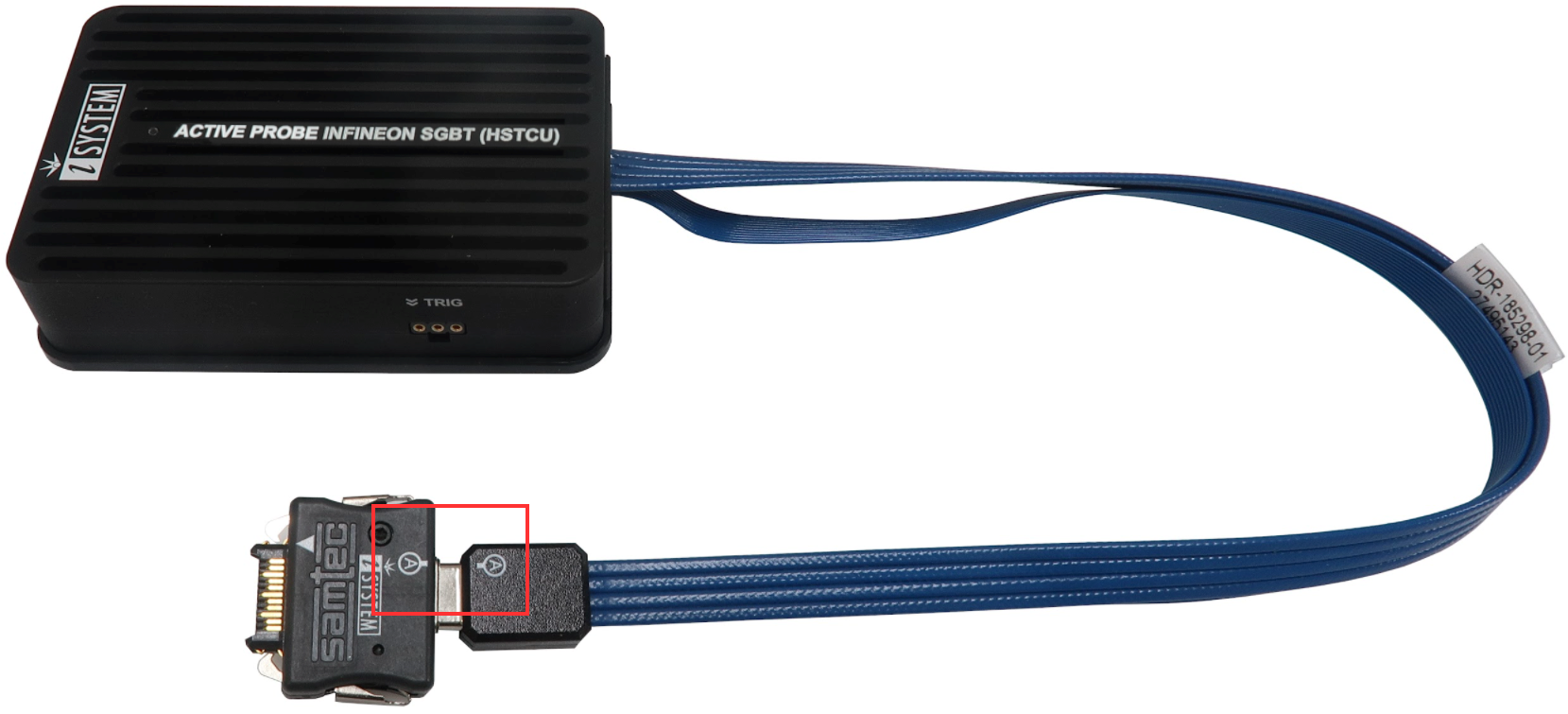
Connecting USB-C converter to the Active Probe
Used physical USB-C type connector doesn’t feature the USB interface as someone could presume (there is no way to incorrectly insert it), but rather the Infineon AGBT (Aurora GigaBit Trace) interface whose signals are connected to the connector in a way that USB-C connector orientation matters.
|
When attaching this converter to the Active Probe, make sure its marking A and marking B is aligned and matches with the markings on the Active Probe connector. |
The following pinout is valid on the target side:
Signal Direction |
Signal Description |
Signal |
Pin |
Pin |
Signal |
Signal Description |
Signal Direction |
|---|---|---|---|---|---|---|---|
I |
AGBT TX0_P |
TX0+ |
1 |
2 |
Vref |
Reference Voltage |
I |
I |
AGBT TX0_N |
TX0- |
3 |
4 |
DAP0 |
DAP Clock |
O |
|
Ground |
GND |
5 |
6 |
DAP1 |
DAP Data |
IO |
|
Not Connected |
NC |
7 |
8 |
NC |
Not Connected |
|
|
Not Connected |
NC |
9 |
10 |
DAP2 |
Optional 2nd DAP data |
I |
|
Ground |
GND |
11 |
12 |
nTRST/DAPEN |
Output |
O |
|
Not Connected |
NC |
13 |
14 |
CLK+ |
AGBT Clock |
O |
|
Not Connected |
NC |
15 |
16 |
CLK- |
AGBT Clock |
O |
|
Ground |
GND |
17 |
18 |
TGO |
AGBT Trigger out |
I |
|
Not Connected |
NC |
19 |
20 |
NC |
Not Connected |
|
|
Not Connected |
NC |
21 |
22 |
nRESET |
Reset |
IO |
Revision A2: Samtec 22-pin ERF8 pinout
Blue colored signals are trace signals.
*Current TriCore devices feature only one AGBT line while the Active Probe hardware is ready for future devices with more AGBT lines.

