Trace Line Calibration
In this topic:
•Indicators in the Trace Line Calibration dialog
•Perform Trace Line Calibration test
Introduction
The Trace Line Calibration dialog provides a view of the signal (trace data) from the trace tool’s perspective. The primary feature of this dialog is a table filled with indicators representing oscilloscope measurements. A trace tool can adjust the sampling position by shifting the sampling voltage and sampling delay in reference to the clock.
The following examples demonstrate how the length of trace lines impacts signal integrity and, consequently, functionality. One typical evaluation board used features a CPU on the upper piggyback board, optionally connected to a lower, larger measurement board via high-quality inter-board connectors.
|
Trace Line Calibration is available only with certain architectures. Note that the Target application must be loaded and running and Parallel trace mode must be selected. |

Indicators in the Trace Line Calibration dialog
The auto-calibration logic automatically determines Recommended values, shown as “R”. However, in cases of significant noise, auto-calibration may not be feasible, requiring manual input of values in the Current input boxes, represented as “o” in the graph.
Indicator |
Description |
|---|---|
. |
Stable signal |
X |
Changing (unstable) signal - signal is traveling from low to high(or opposite) |
o |
Current setting |
R |
Recommended setting |
O |
Optimal setting |
# |
Signal is not changing |
A simple comparison below shows how indicators are translated to the oscilloscope measurements.
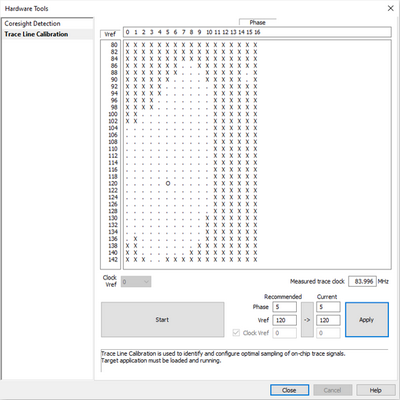
 Trace Line Calibration dialog |
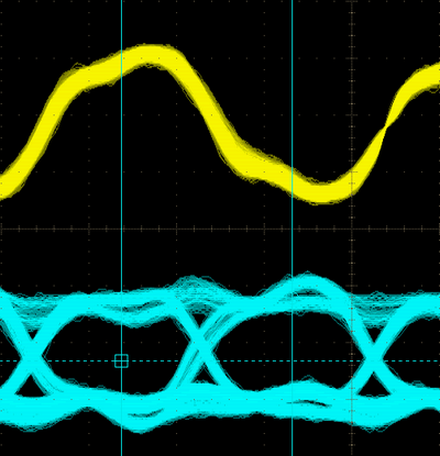
 Indicators represented in the oscilloscope |
Oscilloscope measurements
The oscilloscope shows the same picture measured by the oscilloscope. The yellow line is the trace clock and blue lines the trace data. The dark area within the signal is called the data eye – sampling within this region yields a reliable trace recording.
Trace lines with short stubs
The size of the data eye is large and the tool has no problems in recording the trace.
Trace Line Calibration result |
Measured by oscilloscope |
 |
 |
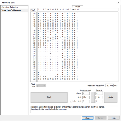
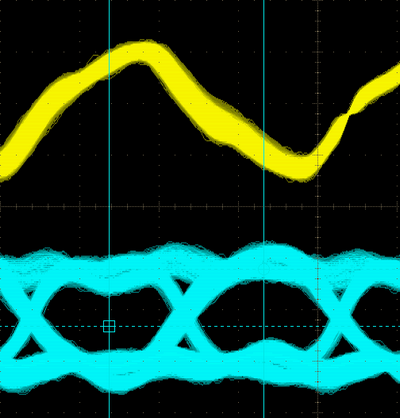
Trace lines with longer stubs (over connector to other board)
By passing through a connector, the data eye shrinks. The auto calibration can still find a safe sampling position, but any additional obstacle (CPU socket, longer PCB lines,…) could shrink the data eye to a point where no safe sampling point could be established.
Trace Line Calibration result |
Measured by oscilloscope |
 |
 |
Perform Trace Line Calibration test
Trace port Calibration test is required due to different trace line lengths. Refer to this chapter for step-by-step instructions.
|
Trace Line Calibration is available only with certain architectures. Note that the Target application must be loaded and running and Parallel trace mode must be selected. |