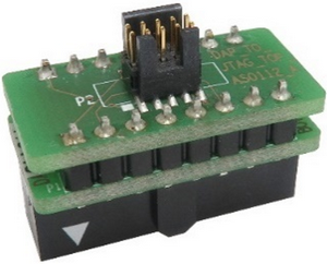
16-pin 2.54 mm Infineon JTAG Converter
When TriCore based target features only a 16-pin JTAG debug connector (no 10-pin DAP debug connector) and you have BlueBox with the 10-pin 1.27mm Infineon DAP2 Wide Debug Adapter, a converter converting 16-pin target JTAG debug connector to 10-pin DAP debug connector is used. DAP debug interface features better performance over the JTAG debug interface. Since the DAP debug interface shares signals with the JTAG debug interface signals, this solution might be even better than the 16-pin 2.54mm Infineon JTAG Debug Adapter.
The following pinout is available on the target side:
Signal Direction |
Signal Description |
Signal |
Pin |
Pin |
Signal |
Signal Description |
Signal Direction |
|---|---|---|---|---|---|---|---|
I/O |
JTAG TMS/DAP Data pin |
TMS/DAP1 |
1 |
2 |
Vref |
Reference voltage |
I |
I/O |
JTAG TDO/Optional 2nd DAP Data pin |
TDO/DAP2 |
3 |
4 |
GND |
Ground |
|
|
Not Connected |
NC |
5 |
6 |
GND |
Ground |
|
|
Not Connected |
NC |
7 |
8 |
nRESET |
Power On Reset |
O |
O |
JTAG nTRST/DAP enable (optional) |
nTRST * |
9 |
10 |
NC |
Not Connected |
I |
O |
JTAG TCK/DAP clock |
TCK/DAP0 |
11 |
12 |
GND |
Ground |
|
|
Not Connected |
NC |
13 |
14 |
NC |
Not Connected |
|
|
Not Connected |
NC |
15 |
16 |
NC |
Not Connected |
|
Required DAP debug interface signals (bold) exposed on the 16-pin JTAG debug connector
Signal Direction is described from the BlueBox perspective.
* nTRST must be connected since the DAP debug interface selection is configured through this signal when nRESET is released.
Connect the converter to the target JTAG debug connector first and then the BlueBox to the converter via the 10-pin 1.27mm Infineon DAP2 Wide Debug Adapter (Ordering code IC50163-2). BlueBox must be configured for DAP debug interface operation in this setup!
|
Make sure this adapter fits on your target connector - check Cross Table. |
|
Refer to Hardware Setup and Configuration Tutorial for more information on how to connect the hardware. |
