10-pin Infineon DAP2 Wide (1.27mm) Debug Adapter
|

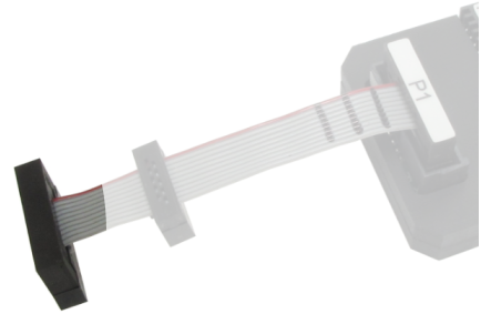
This debug adapter is used to connect the BlueBox to Infineon TriCore and XC2000/XC166 based target featuring a 10-pin 1.27mm pitch target debug connector with Infineon DAP pinout.
The debug adapter connects to the BlueBox through the two ribbon cables and to the target debug connector on the other side.
The following pinout is valid on the target side:
Signal Direction |
Signal Description |
Signal |
Pin |
Pin |
Signal |
Signal Description |
Signal Direction |
|---|---|---|---|---|---|---|---|
I |
Reference Voltage |
Vref |
1 |
2 |
DAP1 |
DAP Data pin |
I/O |
|
Ground |
GND |
3 |
4 |
DAP0 |
DAP clock |
O |
|
Ground |
GND |
5 |
6 |
DAP2 |
Optional 2d DAP Data pin |
I/O |
|
Not Connected |
NC |
7 |
8 |
DAPEN |
DAP Enable |
O |
|
Ground |
GND |
9 |
10 |
nRESET |
Reset |
I/O |
10-pin Infineon DAP pinout
Signal Direction is described from the BlueBox perspective.
|
When initially connecting the BlueBox to a target, ensure the debug adapter pinout matches the Target connector to avoid potential hardware failure. |

Jumper J1
Position 1-2 (default) – Normal debug operation is configured. The debugger drives the MCU reset line low during the initial debug connection and then takes control over the microcontroller.
Position 2-3 – Hot Attach operation is configured. All debug signals from the BlueBox are disconnected and the target starts running as soon as the power is applied to the target. When the Hot Attach command is issued from winIDEA, the debugger connects to the MCU and control over the MCU is taken without resetting the MCU. Refer to the winIDEA Help for more details on the Hot Attach configuration and use.
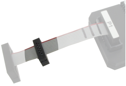
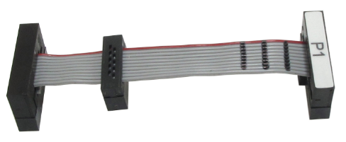
10-pin 1.27mm connectors
|
The debug adapter connects to the target through one of the two 10-pin 1.27mm connectors. Note that only one is to be connected to the target! |
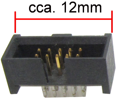
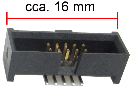
Strain relief
The robust connector (Samtec FFSD-05-01-N-SR) is located at the end of the cable and is the recommended connection connector. It's a bit wider and therefore the target must have a matching part populated. Matching part on the target side is e.g. Samtec ESHF-105-01-L-D (full frame connector) or Samtec FTSH-105-01-F-DV-K (connector without the frame at the side).
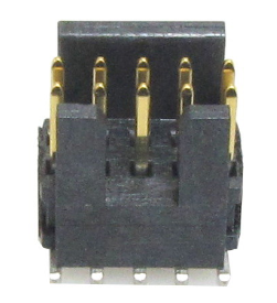
Standard type
The second connector (Samtec FFSD-05-01-N) is 1cm away from the first one toward the BlueBox (Samtec FFSD-05-01-N). It’s much less robust and is prone to fail if the cable is not handled cautiously or just connected/disconnected too many times. This connector should be used when the target doesn’t provide the matching target connector for the Strain relief type connector. Matching part on the target is Samtec SHF-105-01-L-D or Samtec FTSH-105-01-F-DV-K (connector without the frame at the side).
For the target side connector it’s most convenient to use the FTSH-105-01-F-DV-K connector since it matches the connector with and without the Strain relief option.
Target connector |
|
|
|
|---|---|---|---|
|
Robust and less prone to fail |
× |
✓ |
 |
With frame without strain relief (SHF-1xx-01-L-D) |
✓ |
× |
 |
Without frame (FTSH-1xx-01-L-DV) |
✓ |
✓ |
 |
With frame with strain relief (ESHF-1xx-01-L-D) |
✓ |
✓ |
Additional cable
If the 10-pin 1.27mm pitch cable gets damaged or you need longer cables, it can be ordered as a spare part under the ordering code:
•IA10PIN10PIN127
•IA10PIN10PIN127-REV - Reversed connectors
•IA10PIN10PIN127-CUST - Custom cable length must be specified at the order
•IA10PIN10PIN127-CUS1 - Reversed connectors
|
Note that the optional length should be reasonable (e.g. 10 cm) since the quality of electrical signals degrades with prolonging the cable. |
|
BlueBox functionality with this cable, intended for rare situations when the standard debug adapter cannot connect to the target due to physical obstacles, is not guaranteed. Using the BlueBox at lower debug frequency scan speeds without trace functionality may be an acceptable compromise. You should test the BlueBox with a custom-length ribbon cable to ensure compatibility with winIDEA. |
|
Make sure this adapter fits on your target connector - check Cross Table. |
|
Refer to Hardware Setup and Configuration Tutorial for more information on how to connect the hardware. |