ECU14 DAP 10-pin 1.27mm Converter
|

The ECU14 converter and the pinout has been defined by Bosch. The ECU14 DAP 10-pin converter is connecting at the end of the 10-pin 1.27mm Infineon DAP2 Wide D. Adapter (Ordering code IC50163-2) or Infineon DAP/DAPE II Active Probe acting as a pinout converter is available for TriCore targets featuring the ECU14 10-pin 1.27mm target debug connector. It must be ordered separately.
A1 - The following pinout is valid on the target side:
Signal Direction |
Signal Description |
Signal |
Pin |
Pin |
Signal |
Signal Description |
Signal Direction |
|---|---|---|---|---|---|---|---|
|
Ground |
GND |
1 |
2 |
DAP0 |
DAP clock |
O |
|
Not Connected |
NC |
3 |
4 |
DAP2 |
Optional 2nd Data pin |
I/O |
I/O |
DAP Data pin |
DAP1 |
5 |
6 |
nTRST/DAPEN |
Optional 3rd Data pin |
I/O |
|
Not Connected |
NC |
7 |
8 |
Vref |
Reference voltage |
I |
|
Not Connected |
NC |
9 |
10 |
nRESET |
Reset |
O |
Revision A1: 10-pin ECU14 target pinout
A2 - The following pinout is valid on the target side:
Signal Direction |
Signal Description |
Signal |
Pin |
Pin |
Signal |
Signal Description |
Signal Direction |
|---|---|---|---|---|---|---|---|
|
Ground |
GND |
1 |
2 |
DAP0 |
DAP clock |
O |
I/O |
Optional 3rd Data pin |
nTRST/DAPEN |
3 |
4 |
DAP2 |
Optional 2nd Data pin |
I/O |
I/O |
DAP Data pin |
DAP1 |
5 |
6 |
nTRST/DAPEN |
Optional 3rd Data pin |
I/O |
|
Not Connected |
NC |
7 |
8 |
Vref |
Reference voltage |
I |
|
Not Connected |
NC |
9 |
10 |
nRESET |
Reset |
O |
Revision A2: 10-pin ECU14 target pinout
Signal Direction is described from the BlueBox perspective.
|
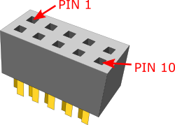
The pin next to the alignment pin is pin 10 and not pin 1! Pin is marked with a number 1 directly on the converter target connector. |
 |

|
Make sure this adapter fits on your target connector - check Cross Table. |
|
Refer to Hardware Setup and Configuration Tutorial for more information on how to connect the hardware. |