Device description
|
|


A – 34-pin ERF8 MPC5xxx/SPC5 target pinout:
Signal Direction |
Signal Description |
Signal |
Pin |
Pin |
Signal |
Signal Description |
Signal Direction |
|---|---|---|---|---|---|---|---|
I |
AGBT TX0_P |
TX0+ |
1 |
2 |
Vref |
Reference Voltage |
I |
I |
AGBT TX0_N |
TX0- |
3 |
4 |
TCK |
JTAG |
O |
|
Ground |
GND |
5 |
6 |
TMS |
JTAG |
O |
I |
AGBT TX1_P* |
TX1+ |
7 |
8 |
TDI |
JTAG |
O |
|
AGBT TX1_N* |
TX1- |
9 |
10 |
TDO |
JTAG |
I |
|
Ground |
GND |
11 |
12 |
nJCOMP |
JTAG TRST (optional) |
O |
|
AGBT TX2_P* |
TX2+ |
13 |
14 |
NC |
Not Connected |
|
|
AGBT TX2_N* |
TX2- |
15 |
16 |
EVTI0 |
Nexus Event Input |
O (not used) |
|
Ground |
GND |
17 |
18 |
EVTO0 |
Nexus Event Output |
I |
|
AGBT TX3_P* |
TX3+ |
19 |
20 |
nPORESET |
Power On Reset |
O |
|
AGBT TX3_N* |
TX3- |
21 |
22 |
nRESET |
Reset |
IO |
|
Ground |
GND |
23 |
24 |
GND |
Ground |
|
|
Not Connected |
NC |
25 |
26 |
AGBT CLK_P |
AGBT Clock |
O |
|
Not Connected |
NC |
27 |
28 |
AGBT CLK_N |
AGBT Clock |
O |
|
Ground |
GND |
29 |
30 |
GND |
Ground |
|
|
Not Connected |
NC |
31 |
32 |
NC |
Not Connected |
|
|
Not Connected |
NC |
33 |
34 |
NC |
Not Connected |
|
34-pin ERF8 MPC5x/SPC5x target pinout
Blue colored signals are Aurora trace signals.
The JCOMP is an optional pin. Some microcontrollers don’t have this pin. Internally, this is actually the JTAG TRST, which resets the JTAG TAP state machine. Because the JTAG TAP state machine can be reset also by the TMS and the TCK, this pin is optional also for the debugger. If the microcontroller has the JCOMP pin but it is not connected to the target debug connector, it must be set to the non-active state in the target via a pull-up resistor. If not, then the JTAG TAP state machine remains in reset and debugging is not possible.
Signal direction definition:
O - Output from the Active Probe to the target microcontroller
I - Input to the Active Probe from the target microcontroller
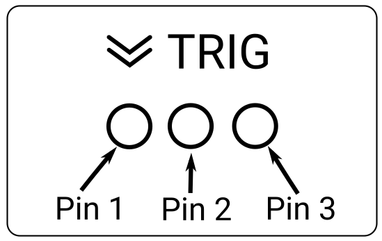
B – mDIO port marked as TRIG on the housing
mDIO port provides two digital signals, which can interact with the embedded target. Each can be configured either for input or output operation.
mDIO port pinout |
mDIO port on the Active Probe |
C – The indicator light provides the status of the Active Probe as follows:
|
Permanently yellow – Initializating. |
|
Permanently green – Powered on and ready to use. |
|
Blinking green – Establishing connection with the BlueBox. |
|
Blinking blue – Reprogramming SPLASH. |
|
Permanently magenta – Golden image loaded and ready to use. |


D – FNet connector, that connects the Active Probe to the iC7max or iC5700. The FNet cable is delivered with the Active Probe.
|
When powering on the system, switch the BlueBox on before powering on the target. When powering down the system, power off the target before powering off the BlueBox! Use only original accessories for powering and connecting with the BlueBox. Consult with technical support before attempting to use any other accessory. |

Target connector
The target should feature a matching part, for example, Samtec part number: ASP-137973-01.