40-pin Samtec / USB-C to USB-C (HSSTP) Switch
|
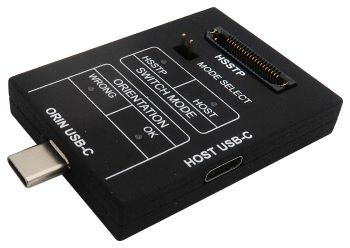
Through this hardware switch, you can conveniently connect:
•Arm HSSTP II Active Probe
•and a host PC via a standard USB-C connection
to NVIDIA Orin or Thor device (connection marked as TARGET USB-C) at the same time. This switch is optional and must be ordered separately.
A use case is that an application is programmed by the PC-based flash programming utility through the USB-C connection, and later, the application is debugged using the ARM HSSTP II Active Probe. Refer to the Switch NVIDIA Orin or Thor USB port functionality with mDIO port for a use case where the switching can be automated.
Switch configuration
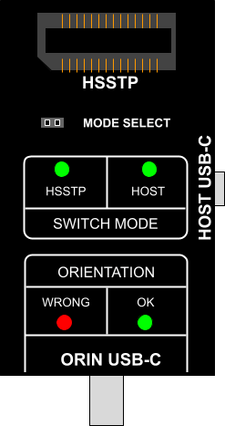
MODE SELECT jumper defines which connection is active.
Selected |
Description |
MODE SELECT jumper |
SWITCH MODE indication |
|---|---|---|---|
HOST USB-C |
USB connection between the PC and the NVIDIA Orin or Thor device is established. |
Not populated / not bridged. |
The HOST LED is ON. |
HSSTP (default) |
USB-C is configured for SWD + HSSTP operation to which ARM HSSTP II Active Probe is connected. |
Bridged. |
The HSSTP LED is ON. |
Connectors
The switch features two USB-C connectors:
•TARGET USB-C with a custom pinout for connection with the NVIDIA Orin or Thor device,
•HOST USB-C for connection with the host PC (standard USB connection).
The following pinout is valid on TARGET USB-C connector in HOST mode:
Signal Direction |
Signal Description |
Signal |
Pin |
Pin |
Signal |
Signal Description |
Signal Direction |
|---|---|---|---|---|---|---|---|
|
Ground |
GND |
A1 |
B12 |
GND |
Ground |
|
|
USB 3.0 SSTX |
TX1_P |
A2 |
B11 |
RX2_P |
USB 3.0 SSRX |
|
|
USB 3.0 SSTX |
TX1_N |
A3 |
B10 |
RX2_N |
USB 3.0 SSRX |
|
|
USB +5V Supply |
VBUS |
A4 |
B9 |
VBUS |
USB +5V Supply |
|
|
Configuration Channel |
CC1 |
A5 |
B8 |
SBU2 |
Alternative Mode |
|
|
USB 2.0 data |
D1_P |
A6 |
B7 |
D1_N |
USB 2.0 data |
|
|
USB 2.0 data |
D1_N |
A7 |
B6 |
D1_P |
USB 2.0 data |
|
|
Alternative Mode |
SBU1 |
A8 |
B5 |
CC2 |
Configuration Channel |
|
|
USB +5V Supply |
VBUS |
A9 |
B4 |
VBUS |
USB +5V Supply |
|
|
USB 3.0 SSRX |
RX2_N |
A10 |
B3 |
TX2_N |
USB 3.0 SSTX |
|
|
USB 3.0 SSRX |
RX2_P |
A11 |
B2 |
TX2_P |
USB 3.0 SSTX |
|
|
Ground |
GND |
A12 |
B1 |
GND |
Ground |
|
ORIN/Thor USB-C pinout in HOST mode
The following pinout is valid on TARGET USB-C connector in HSSTP mode:
Signal Direction |
Signal Description |
Signal |
Pin |
Pin |
Signal |
Signal Description |
Signal Direction |
|---|---|---|---|---|---|---|---|
|
Ground |
GND |
A1 |
B12 |
GND |
Ground |
|
I |
HSSTP Lane 0 |
TX0_P |
A2 |
B11 |
NC |
Not Connected |
|
I |
HSSTP Lane 0 |
TX0_N |
A3 |
B10 |
NC |
Not Connected |
|
|
Reference Voltage |
VREF |
A4 |
B9 |
VREF |
Reference Voltage |
|
|
Configuration Channel* |
CC1 |
A5 |
B8 |
SBU2 |
Cable Orientation |
|
O |
SWD |
SWCLK |
A6 |
B7 |
NC |
Not Connected |
|
IO |
SWD |
SWDIO |
A7 |
B6 |
NC |
Not Connected |
|
|
Cable Orientation |
SBU1 |
A8 |
B5 |
CC2 |
Configuration Channel* |
|
|
Reference Voltage |
VREF |
A9 |
B4 |
VREF |
Reference Voltage |
|
|
Not connected |
NC |
A10 |
B3 |
TX1_N |
HSSTP Lane 1 |
I |
|
Not connected |
NC |
A11 |
B2 |
TX1_P |
HSSTP Lane 1 |
I |
|
Ground |
GND |
A12 |
B1 |
GND |
Ground |
|
ORIN/Thor USB-C pinout in HSSTP mode
* Pulled down with 5k1 resistor.
Blue colored signals are trace signals.
The following pinout is valid on HOST USB-C connector:
Signal Direction |
Signal Description |
Signal |
Pin |
Pin |
Signal |
Signal Description |
Signal Direction |
|---|---|---|---|---|---|---|---|
|
Ground |
GND |
A1 |
B12 |
GND |
Ground |
|
|
USB 3.0 SSTX |
TX1_P |
A2 |
B11 |
RX1_P |
USB 3.0 SSRX |
|
|
USB 3.0 SSTX |
TX1_N |
A3 |
B10 |
RX1_N |
USB 3.0 SSRX |
|
|
USB +5V Supply |
VBUS |
A4 |
B9 |
VBUS |
USB +5V Supply |
|
|
Configuration Channel |
CC1 |
A5 |
B8 |
SBU2 |
Alternative Mode |
|
|
USB 2.0 data |
D1_P |
A6 |
B7 |
D2_N |
USB 2.0 data |
|
|
USB 2.0 data |
D1_N |
A7 |
B6 |
D2_P |
USB 2.0 data |
|
|
Alternative Mode |
SBU1 |
A8 |
B5 |
CC2 |
Configuration Channel |
|
|
USB +5V Supply |
VBUS |
A9 |
B4 |
VBUS |
USB +5V Supply |
|
|
USB 3.0 SSRX |
RX2_N |
A10 |
B3 |
TX2_N |
USB 3.0 SSTX |
|
|
USB 3.0 SSRX |
RX2_P |
A11 |
B2 |
TX2_P |
USB 3.0 SSTX |
|
|
Ground |
GND |
A12 |
B1 |
GND |
Ground |
|
HOST USB-C pinout
Signal Direction is described from the BlueBox perspective.
|
When initially connecting the BlueBox to a target, ensure the debug adapter pinout matches the Target connector to avoid potential hardware failure. |

Orientation
When connecting the switch TARGET USB-C connector to NVIDIA Orin or Thor target, make sure the connector is oriented correctly. Pay attention to the ORIENTATION LED indicator located on the Switch. The green LED lits when ORIN USB-C connector is properly connected to the NVIDIA target. If the red LED lits, rotate the ORIN USB-C connection.
• Red – Wrong
• Green – OK