Switch NVIDIA Orin/Thor USB port functionality with mDIO port
In this topic:
•Using the Active Probe mDIO port to automate the Switch mode selection
•How to measure Debug I/O levels
Introduction
This topic describes how to use the 40-pin Samtec / USB-C to USB-C (HSSTP) Switch and how to automate NVIDIA Orin/Thor (TARGET) USB port switching between HSSTP and device mode with BlueBox tools.
The USB port of the NVIDIA Orin/Thor can be used for:
•Debug and trace via HSSTP
•Device USB connection
The 40-pin Samtec / USB-C to USB-C (HSSTP) switch simplifies switching between the two modes of the USB port.
MODE SELECT jumper
Switching of the USB port mode is done by the MODE SELECT jumper:
•If the jumper is not bridged, the Switch is in HOST mode. This means that the TARGET USB-C port is connected to the HOST USB-C port.
•If the jumper is bridged, the Switch is in HSSTP mode. This means that the TARGET USB-C port is connected to the HSSTP connector.
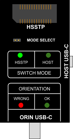
Status LEDs
Status LEDs on the switch show the currently connected configuration.
1. The HOST USB-C port is connected to the TARGET USB-C port.
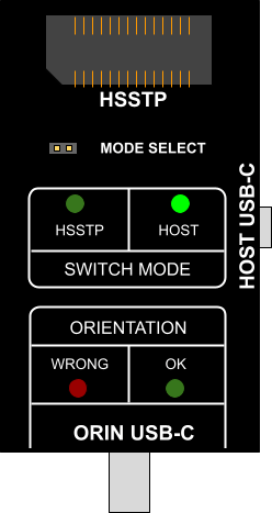
2. The HSSTP port is connected to the TARGET USB-C port, the orientation of the USB-C cable to the TARGET USB-C port is correct.
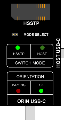
The HSSTP port is connected to the TARGET USB-C port, the orientation of the USB-C cable to the TARGET USB-C port is wrong. Reverse one side of the cable.
Requirements
•winIDEA 9.21.118 or newer
•iC7max/iC5700 BlueBox
•Arm HSSTP II Active Probe
•40-pin Samtec / USB-C to USB-C (HSSTP) switch
•mDIO Cable
Using the Active Probe mDIO port to automate the Switch mode selection
Each time when a mode change is necessary, you can avoid manually placing and removing the MODE SELECT jumper cap by using the Active Probe mDIO port. In this way, the mode change will be automated. You can do this by connecting setup and winIDEA configuration. The result of the process will be as follows:
1. When you try to connect from winIDEA (Attach, Reset or Download) to the target, the switch will automatically connect the TARGET USB-C port to the HSSTP connector.
2. When winIDEA will be detached from the target, the Switch will automatically connect the TARGET USB-C port to the HOST USB-C port.
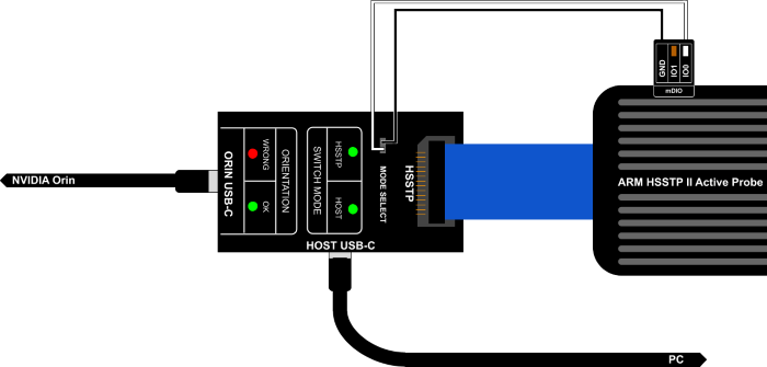
How to connect the hardware
Connect the following on the Switch
•Arm HSSTP II Active Probe to HSSTP connector
•USB cable connected to the PC to HOST USB-C connector
•USB-C cable connected to the TARGET USB-C port to TARGET USB-C connector
•GND pin of Arm HSSTP II Active Probe mDIO to pin 2 (left) of MODE SELECT jumper
•IO0 pin of Arm HSSTP II Active Probe mDIO to pin 1 (right) of MODE SELECT jumper
Configuration steps
This procedure needs to be done only once. After the configuration is saved to the winIDEA workspace, Switch control via BlueBox tools will be done automatically.
1. Perform Debug > Prepare to Attach.
2. Configure mDIO pin D0_0 as an output pin with the initial state LOW.
3. Go to Hardware > SoC Options > Hardware and select appropriate Debug I/O levels* instead of Vref.
|
* Set an appropriate “Debug I/O levels” value to avoid misconfiguration, which can cause the target damage. |

4. Confirm and save your workspace.
How to measure Debug I/O levels
1. Connect the Switch to the NVIDIA Orin/Thor SoC and the Arm HSSTP II Active Probe.
2. Bridge both pins of the MODE SELECT jumper with the jumper cap.
3. In winIDEA, make a connection to the target, and measure Vref in Measurement plugin.
More resources
•mDIO use cases and configuration