mDIO Use case Configuration
In this topic:
•Synchronous observing via Analyzer Profiler Timeline Window
Introduction
The mDIO port is located on the side of the iC7 BlueBox Debugger family or a specific Active Probe. It provides digital signals, which can interact with the embedded target. Each signal can be configured either for input or output operation. mDIO cable or test clips are used to connect the mDIO port with the signals around the debugged microcontroller, which can then be either read or controlled by the debugger.
 iC7max BlueBox front view with mDIO port |
 iC7mini /iC7pro BlueBox front view with mDIO port |
 Active Probe Infineon DAP/DAPE II with mDIO port |
Requirements
•iC7max/iC7mini/iC7pro/iC5700 BlueBox
oiC7max: Active Probe with mDIO port, mDIO cable
oiC7mini/iC7pro: iC7 Adapter, Test clips, winIDEA version 9.21.215 and newer
oiC5700: Active Probe with mDIO port, mDIO cable, winIDEA version 9.21.118 and newer
Functionalities
Pin toggling and triggering
mDIO allows you to toggle the pin states using TC triggers. Additionally, the pin state can act as a trigger itself. This means that a trigger event can change a pin's state from one to zero or vice versa. You can also set a pin as an input and use its transition from high to low or low to high as a trigger event.
HIL control
mDIO can be conveniently controlled via winIDEA. You can manually toggle pins, observe their states, and configure initial pin states and directions via Hardware-in-the-Loop (HIL) monitor which facilitates hands-on control and automation for test scenarios.
Pattern generation
mDIO includes a pattern generator feature, enabling the generation of arbitrary digital signals with specific patterns. This capability is useful for generating digital frequencies, PWM patterns, and other custom signal patterns required for testing and analysis purposes.
Automation
The mDIO port is fully controllable via winIDEA SDK and therefore it can be used for test automation.
Use cases
Power control
mDIO can be employed for power cycling a target device, especially when it enters an unrecoverable state. By automating the power control process, you can perform tests and analyze code execution during power cut scenarios.
 Power control block diagram for iC7mini/pro BlueBox use case |
 Power control block diagram for Active Probe with iC7max/iC5700 BlueBox use case |
Check this topic Target power control using BlueBox & ADIO for more information.
Watchdog handling
It can be utilized to put the watchdog chip into test mode, preventing unwanted chip resets. Its ability to change polarity simplifies compatibility with different chips, eliminating the need for external inverters.
 Watchdog handling block diagram for iC7mini/pro BlueBox use case |
 Watchdog handling block diagram for Active Probe with iC7max/iC5700 BlueBox use case |
HIL monitoring
With mDIO, you can manually control the target state, including program inputs. Emulating limit switches or push buttons becomes easier by connecting mDIO to the target's pin. This method enables functional testing without the need for physical switches.
 HIL monitoring block diagram for iC7mini/pro BlueBox use case |
 HIL monitoring block diagram for for Active Probe with iC7max/iC5700 BlueBox use case |
Frequency communication
The mDIO's pattern generation capability allows the transmission of different frequencies to represent distinct signal levels. By controlling the timing and triggers, engineers can communicate with external devices using specific frequencies, facilitating testing and analysis.
Configuration
General
|
Create a new workspace via File | Workspace | New. |

|
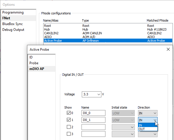
Make sure your BlueBox | Active Probe IN and OUT is properly configured via Hardware | Options | FNet. |

|
Perform Reset | Download. |

|
Configure your workspace: |

•Synchronous observing via Analyzer Profiler Timeline (iC5700 BlueBox and Active Probe)
•Pattern generation (iC5700 BlueBox and Active Probe)
Pin toggling
You can use triggers to toggle the pins.
|
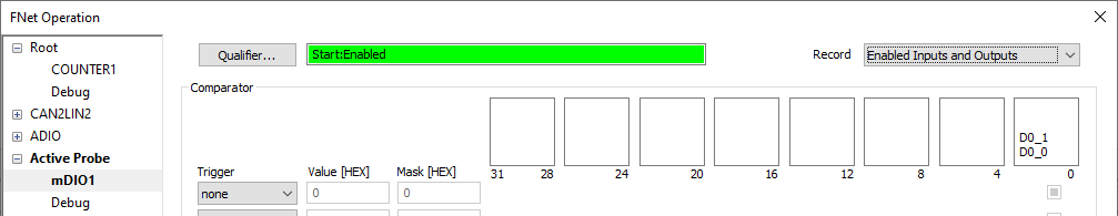
Open Hardware | FNet Operation and select the mDIO page. |
|
Configure the actions and triggers as desired. |

|
Run the application. |
HIL monitoring
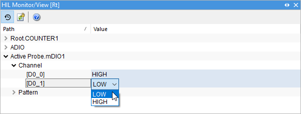
If you Run, Reset, or Prepare to attach you can use the HIL Monitor.
|
Open via View | HIL Monitor | View. |
|
Enable Real-time monitoring. |
|
Run the application. |
|
To observe the values via Watch Window, you can simply drag and drop [D0_n] to the Watch Window pane. |
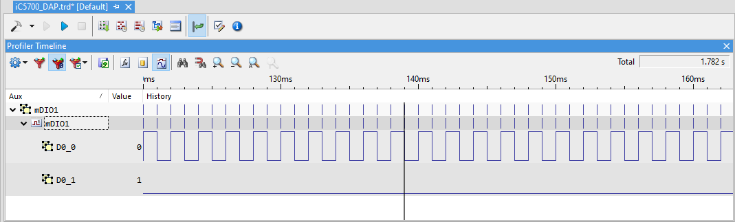
Synchronous observing via Analyzer Profiler Timeline Window
|
Supported on iC7pro/iC7max/iC5700 BlueBox. |
|
Open the Analyzer via View | Analyzer | Analyzer Configuration. |
|
On the Recorder page enable Upload while sampling and Generate time sync messages. |
|
Enable FNet and press Configure. |
|
Configure mDIO page: |
•Enable Qualifier | Recording is enabled from start.
•Select Enabled Inputs and Outputs in the Record drop-down.
|
Make sure the AUX signals are visible in the Profiler Timeline. |

|
Start the Analyzer session. |

winIDEA SDK Example
You can fully automate mDIO port using winIDEA SDK.
More resources
•Active Probes - Hardware User Manuals
•Network description - mDIO port general configuration
•mDIO - Pattern Generator