mDIO Pattern Generator
In this topic:
This chapter describes configuration of pattern generation via mDIO port located on specific Active Probes.
Requirements
•iC7max/iC5700 BlueBox
•Active Probe *
|
* Please refer to your Hardware User Manual if mDIO is available on your Active Probe. |
Features
•2 independent generators •2 digital outputs •1 us resolution (max 1000 s duration) •max 512 frames per generator |
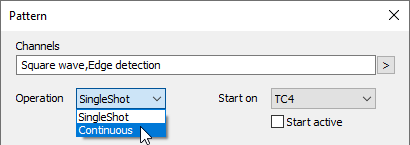
•Multiple modes of operation: oContinuous / Single shot oStart active / Start on FNet Trigger oStop immediately / Finish patterns |
Configuration
|
Configure Active Probe via Hardware | Options | FNet. |

|
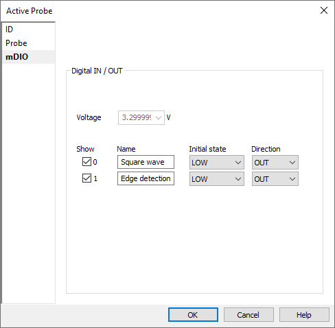
Double-click on your Active Probe and configure mDIO. |

Set the Direction of the channel to OUT and optionally name the mDIO pins according to their use.
|
Configure pattern generation via Hardware | FNet Operation | Active Probe | mDIO1. |

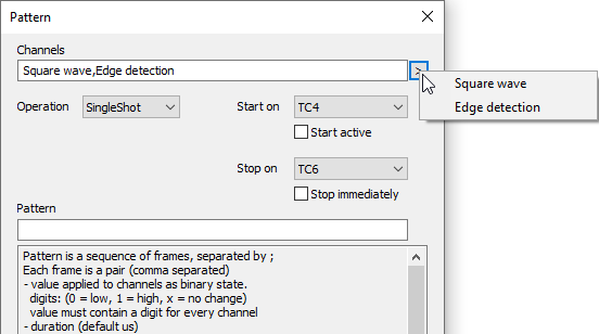
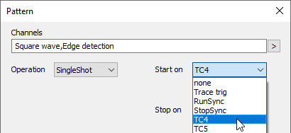
Select Channels - active pins, e.g. Square wave, Edge detection, via the arrow button. Make sure pins are used only in one pattern generator. The pins are set in the order as indicated in the Channels field. From the Pattern section, open the individual channel Pattern dialog with click on the three-dots button.
|
Select the Operation mode. |

|
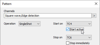
Configure Start and Stop position. |

Start active - Play the pattern immediately when the Operation is confirmed and the dialog is closed. If the option is not checked it will start on a selected trigger.
Stop immediately - If this option is set, pattern will stop immediately when TCx is received, otherwise pattern will be played till the end.
|
Select the Start and Stop on FNet triggers (optional). |

Select the triggers from the drop-down.
•Start on - The current pattern is finished immediately the generator is stopped.
•Stop on - The trigger stops the playback. Pattern plays till end if Stop immediately isn't selected.
You can inject these triggers manually via Hardware / Inject FNet triggers.
|
Input the pattern. |

Pattern is a sequence of frames (states on the pins - ones and zeros), separated by a semicolon - ";".
Each frame is a pair (comma separated) and it consist:
•Masked Value
•Duration (1 us resolution - default)
Value is applied to Channels as a binary state and it must contain a digit (0 = low, 1 = high, x = no change) for every Channel.
Example 1
Assuming 2 channels (D0_1, D0_0) are specified this the pattern description:
01,140; x0,10; 1x,50ms; 11,100us |
Frame 1 will: •Set 1 > D0_0 •Set 0 > D0_1 •Wait for 140 us |
Frame 2 will: •Set 0 > D0_0 •Wait for 10 us |
Frame 3 will: •Set 1 > D0_1 •Wait for 50 ms |
Frame 4 will: •Set 1 > D0_0 •Set 1 > D0_1 •Wait for 100 us |
Example 2
Assuming 1 channel (D0_0):
2*(1,1us; 0,2us) |
1 >D0_0, wait 1 us
0 >D0_0, wait 2 us
1 >D0_0, wait 1 us
0 >D0_0, wait 2 us