Texas Instruments
In this topic:
•CC2650: SWO pin configuration
•AWR18xx and AWR68xx: Soft Reset
CC2650: SWO pin configuration
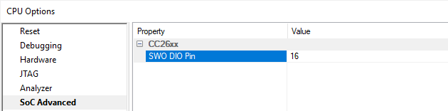
CC265xx device supports configuring the DIO pin on which SWO trace is output.
1. Specify which IO port to use for Serial Wire Output in Hardware / CPU Setup / SoC Advanced page.
2. SWO output must be connected on TDO pin of the ARM or CORTEX adapter. Since JTAG protocol uses TDO for debug communication, SWO can only be captured when cJTAG debug protocol is selected in winIDEA.
AWR18xx and AWR68xx: Soft Reset
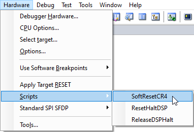
Texas Instruments AWR18xx and AWR68xx devices need to have the ROM eclipsed with the RAM content after the bootloader. ROM eclipsing needs to be enabled manually, followed by a soft reset. In Hardware / Scripts, use the provided SoftResetCR4 script to execute the soft reset of the chip. After the reset, retry the download.
TMS570: ECC functionality
Flash on TMS570 devices features an ECC functionality. ECC area can be programmed automatically with values corresponding to downloaded data or user can provide own ECC download data. Option for automatic ECC generation is located in Hardware / TI TMS570 / Configure / Configuration in the Device dialog.
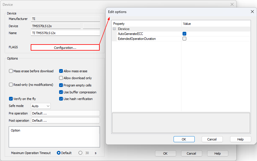
AutoGenerateECC - When checked ECC area can be programmed automatically with values corresponding to the downloaded data. Automatic ECC generation is suggested for a faster download. User can still provide own ECC download data and by enabling Verify in Debug / Files For Download / Options pane to ensure that data written to ECC area matches the downloaded data.
ExtendedOperationDuration - Extends the timeout for flash operations on some devices.
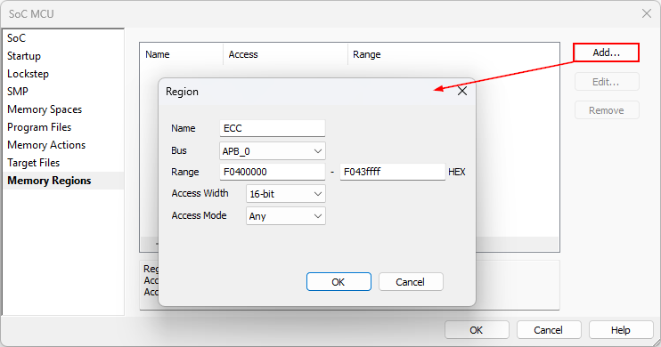
Reads from ECC
Reads from ECC area must be done with 16-bit accesses. Open Debug / Configure Session / SoCs / Memory Regions.
CPU Clock
Internal flash programming monitor is made with flash programming library from TI. The library must be initialized with correct CPU frequency for proper timings generation. The value for the CPU frequency is taken from Hardware / CPU Options / Debugging / CPU clock setting.
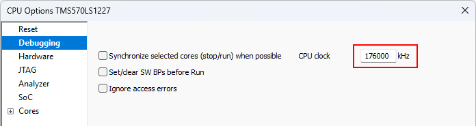
|
The same value is used for download operations and for the memory writes through memory window during debug session. Use initialization sequence to set CPU clock to final value before download to be enable to make flash writes anytime. |
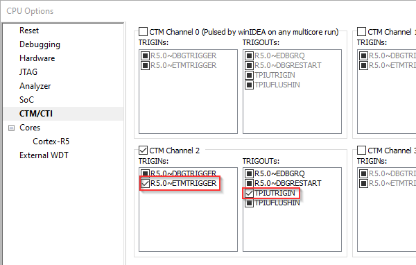
TMS570LC4357: Trace Triggers
User should configure below settings in CTM/CTI dialog for trace trigger to work correctly.
1. Open Hardware menu / CPU Options / CTM/CTI page.
2. Check R5.0 ˜ETMTRIGGER in CTM Channel 2 / TRIGINs section.
3. Check TPIUTRIGIN in CTM Channel 2 / TRIGOUTs section.
 |