DIO
This chapter describes how to triggers and/or generate actions, generate a certain voltage level when a trigger occurs etc. with the ADIO module.
DIO module can be used to create a trigger and/or generate an action, when a trigger occurs, e.g. generate a pattern on a output channel.
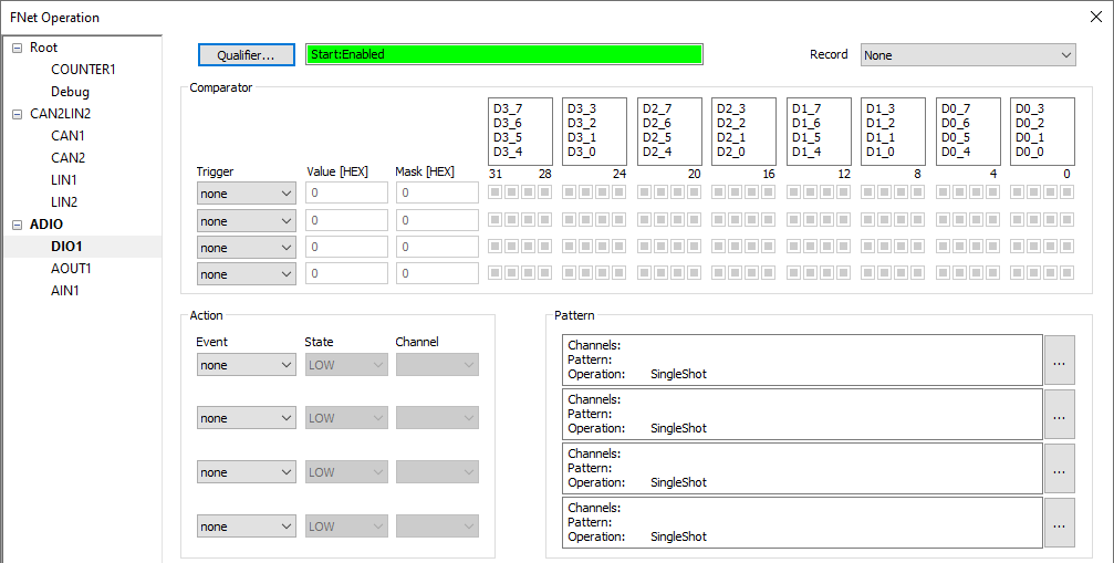
Qualifier - To enable DIO module recording set qualifier:
•Enable from the start
•Enable on specified event
•Disable on specified event
Record - DIO module can be configured to record:
•None
•Enabled Inputs - Inputs, which are enabled in Network description dialog
•Enabled Inputs and Outputs - Inputs and outputs, which are enabled in Network description dialog
Comparator
DIO input channels can be used to create an FNet trigger:
•Trigger line - Select the line you wish to trigger
oNone - Trigger is disabled
oPredefined trigger (Trace trig, RunSync, StopSync)
oCustom trigger (TC4....TC10)
•Value and Mask - Use the graphical user interface on the right to determine the combination of input signals on which you wish to trigger. Note that  symbol means that this signal is ignored
Action
DIO output channels can be used to perform an action when a trigger occurs:
•Event Line - Select the line which will trigger the action.
oNone - Action is disabled
oPredefined action (Trace trig, RunSync, StopSync)
oCustom action (TC4....TC10)
•State - Select low or high channel state
•Channel - Select channel, where action is performed
Pattern
Patterns can be defined for DIO output channels
•Channels - Select channels for specified patterns
•Pattern - Define pattern for selected channels
Detailed explanation available in the pattern dialog