SoC
In this topic:
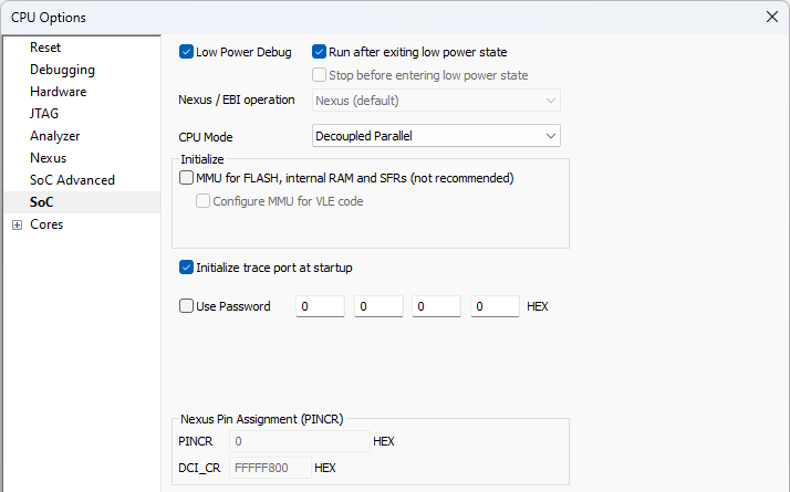
Open Hardware | CPU Options | SoC.
As depicted this option is relevant for:
The PowerPC SoCs that have 2 cores (Multicore Leopard SoCs (SPC56EL44, SPC56EL50, SPC56EL54, SPC56EL70),Multicore Komodo SoCs (MPC5673K, MPC5674K, MPC5675K, PXS3010, PXS3015, PXS3020)), that can be configured to either work in:
•Lockstep mode - both cores are executing same instructions in parallel (better safety). They are debugged as if it was one core in SoC - winIDEA displays one core.
•Decoupled mode - each core is executing its own code (better performance). They are debugged separately - winIDEA displays two cores.
Changing this option won't change Operation Mode in SoC, this is set in SoC flash by user. This option will only tell winIDEA how to handle this SoC.
MMU for FLASH, internal RAM and SFRs (not recommended)
Under some circumstances the user may use Hardware | CPU Options | Cores | Address (Preset PC after stopped in init) after the debug download or debug CPU reset. In such case, BAM code, which is otherwise executed by the CPU and configures MMU among other things, is skipped and the CPU program counter preset. Consequentially, program counter points to the address range for which the MMU is not configured and the debugger pops up an error “MMU TLB Entry for this address not found. Ensure correct MMU configuration«. To overcome this problem, check the Initialize MMU for FLASH, internal RAM and SFRs option in order for the debugger to configure the MMU after the CPU reset instead of the BAM code.
Note that when Address (Preset PC after stopped in init). address points to VLE code section, the Configure MMU for VLE code option should be checked too. Some devices support PowerPC instruction set only, some VLE instruction set only and some both instruction sets. Refer to the reference manual of your particular device for supported instruction set(s).
|
It is not recommended to use Address (Preset PC after stopped in init) address after the debug download or the debug CPU reset unless the user is really aware of the consequences skipping the BAM and application startup code. It can easily happen that application being debugged with this option checked will not run in standalone. |

Initialize trace port at startup
On some CPUs, certain CPU registers must be configured before Nexus trace can be used
This option is available only for certain devices (e.g. Bolero, Leopard, Calypso, Race Runner devices) and allows unlocking the CPU which was previously locked. Some devices are already password protected when new or they may be locked later on by writing a password to specific memory regions.
|
It is recommended that the CPU goes through the power on reset after programming a new password. On certain devices it has been noticed that when changing the password, the debugger could not attach to the microcontroller with a valid password until the target was switched off and on. |
Enable this option and enter the 16-bit values combining a valid password to unlock it. If your device is password protected by device manufacturer contact the manufacturer to obtain the valid password.
64-bit passwords
Might be swapped. If the password is being swapped, the user has to swap lower and higher 32-bit values when entering the password in winIDEA (compared to the password that was written to / UTEST memory). For example:
Value written to Shadow memory: 0123 4567 89AB CDEF |
256-bit passwords
Always swapped and winIDEA therefore swaps the password by default. In this case enter the value exactly as it was written in the UTEST memory.

Devices with 256-bit passwords can be unlocked by using RESET method Stop functionality, because after the reset release the chip needs to be stopped. For more information refer to Knowledge Base.
|
If Use Password is enabled, Mass Erase in the Hardware | Flash | Mass Erase is automatically disabled. Otherwise some devices could be permanently locked. |
Certain microcontrollers (e.g. SPC570S50L) can have Nexus signals routed to different physical pins. This routing is configured through the registers, which are not memory mapped and accessible only through the debug interface. User must set value of the PINCR and DCI_CR register according to his specific target application. The debugger will configure these registers when Nexus port is being used. Refer to the microcontroller’s reference manual for more information on Nexus pin assignment.