Debug SCR
In this topic:
•Enabling the SCR core via SoC DAP
•Debugging the SCR as a primary SoC
Introduction
A Standby Controller (SCR) is an 8-bit microcontroller based on 8051 architecture and can continue to run also during the standby mode. It's available on selected TC3xx devices. The SCR SoC is selectable for debugging in winIDEA as any other SoC.
Before you can start debugging the SCR core via SoC DAP or as the primary core via the Private DAP interface, the chip must be properly enabled and configured.
The SCR SoC can be debugged via:
•SoC DAP port (regular DAP debug port)
This port operates at up to 160 MHz frequency. When debugging the SCR SoC make sure you use DAP standard and work at 10 MHz DAP clock or lower, since this is the restriction of the SCR. Regular debugging of other AURIX cores through this port works up to 160 MHz DAP clock - if the embedded target is designed (PCB layout) properly.
•Private DAP port, called SCR DAP and has access to the SCR only. Other AURIX cores are not accessible through this port. Make sure you use DAP standard and work at 10 MHz DAP clock or lower.
Both ports work with the BlueBox debugger:
•iC5000/iC5700/iC7mini/iC7pro via Debug Adapter
•iC5700/iC7max with Infineon Active Probe
Before connecting the debugger, double check on the embedded target what DAP port is exposed on the physical debug connector.
SoC DAP port - Marked with yellow rectangle.
Private DAP port - Marked with green rectangle.

Enabling the SCR core via SoC DAP
Before you can start debugging the SCR core via the SoC DAP interface, the device must be properly configured.
|
Select DAP Standard Debug channel Mode via Hardware | CPU Options | SoC. |

|
Max DAP frequency is 10MHz! When using the SoC DAP port for SCR SoC debugging, only the DAP Standard mode can be used. You can't debug the SCR core via the main cores via SoC DAP port in a low power mode. |

|
Use an initialization script. |

The SCR core can be enabled via an initialization script, which is added to Hardware | CPU Options | Reset | Initialization before Programming and configures two registers.
Script example:
A PMS_PMSWCR4 L 0x030A0023 |
Writing to the PMS_PMSWCR4 register via the initialization script enables the SCR and SoC DAP mode. Writing 0xFFFFFFFF to the PMS_PMSWSTATCLR register clears all status registers. All general purpose registers on the SCR core are memory mapped to first 255 bytes of the memory.
Standard SFR Symbols of the TC3xx
Step A |
Step B |
|
|---|---|---|
ACC |
0E0H |
0E0H |
B |
0F0H |
0DDH |
SP |
081H |
0D4H |
DPL |
082H |
0D5H |
DPH |
083H |
0D6H |
|
The SCR SoC is slightly modified in Step B of the TC3xx devices comparing to Step A. One revision of the compiler is used to generate the SCR code for Step A of the TC3xx chip, while different revision is used to generate the SCR code for Step B of the chip. Refer to the AURIX Reference Manual for more information. |
|
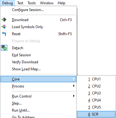
Selecting the SCR core via secondary winIDEA instance Debug | Core | SCR. |

The SCR must start in one of the OCDS modes. Start-up is controlled by the SCRCFG bits in the Standby and Wake-up Control Register 4. When the SCR is started in OCDS SoC DAP mode, the SCR is considered as a secondary core in winIDEA and is debugged through the same (SoC) debug interface as all other TriCore/HSM cores.
Debugging the SCR as a primary SoC
When the SCR is started in OCDS SCR DAP mode, then the SCR debugging is possible via Private DAP interface. Target board must have a Private DAP debug connector where the debugger is connected to debug the SCR via Private DAP interface.
|
Select DAP Standard Debug channel Mode via Hardware | CPU Options | SoC. |
|
Max DAP frequency is 10 MHz! When using the SoC DAP port for SCR SoC debugging, only the DAP Standard mode can be used. |
|
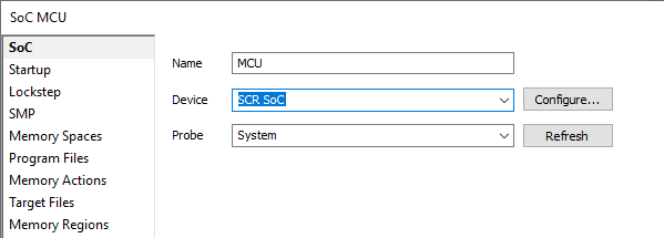
Select SCR SoC via Debug | Configure Session | SoCs | SoC. |
This will result in the SCR as the primary SoC.
|
Add INI file to Hardware | CPU Options | Reset | Initialization before Programming. |
To debug SCR core via private DAP, an application running TriCore code must properly configure ports and PMS_PMSWCR4 register. The same can be also configured via INI file executed on the TriCore side.
Which debug pins are used is selectable in the PMS_PMSWCR4 register.
•If SCR debugging is done via SCR DAP0_0 and DAP1_0 pins, use the following INI file:
A P33_PCSR L 0x000000FF |
 Boot Modes
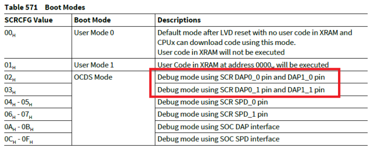
•If debugging via SCR_DAP0_1 pin and DAP1_1 pin is used, then use the following ini file:
A P33_PCSR L 0x000000FF |