SoC
This chapter enables a selection of Debug channel, Trace Buffer, Use Password settings. Open Hardware | CPU Options | SoC.
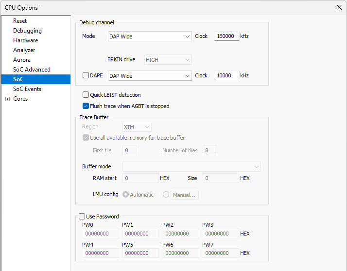
Debug channel
Mode
Select debug mode according to the debug interface you use.
•JTAG
•DAP Standard
•DAP Wide
•DXCPL (DAP over CAN Physical Layer Converter)
|
DAP debug interface is recommended because it provides better performance. |
Clock - Select DAP Clock, if you use DAP Standard or DAP Wide debug interface. Typical DAP Clock is in the range between 10 to 160 MHz.
DAPE
AURIX TC3xx and TC4x emulation devices feature DAPE trace interface, which provides access to the on-chip MCDS trace module and increases the bandwidth of the trace channel toward the debugger.
Quick LBIST detection
Enable this option if your application engages LBIST during runtime to allow for quicker re-attach to the SoC.
Flush trace when AGBT is stopped
When Trace FIFO isn’t full, it is not flushed automatically. If nothing is being recorded, check this option. This option is available on iC7max/iC5700 BlueBox in conjunction with Infineon AGBT Active Probe.
Trace Buffer (TC2xx and TC3xx)
Region
Select a region of (EMEM): TCM (Trace/Calibration Memory) or optional XTM (Extended Trace Memory)
Use all emulation memory for trace buffer
Enabled by default. In this case, all memory is used for trace.
First tile / Number of tiles
When the memory is split between the calibration and the trace, allocate, which tiles are available for the trace. The trace requires a block of consecutive tiles. Define the first tile and define number of tiles available for trace.
If the target application uses the same memory tiles, which were allocated for tracing, trace could behave unexpectedly or would not work at all.
•Upload while sampling (UWS) - Minimum of 2 EMEM tiles is required. However, it is recommended to allocate a minimum of 3 EMEM tiles for trace.
•AGBT Streaming - In this case an XTM tile is used as a FIFO within the AGBT trace data path. The AGBT uses the two XTM files as FIFO. For additional information, refer to Analyzer Overview.
Buffer mode - Configure the mode in which the trace buffer should operate.
RAM Start and Size - Specifies the range of internal RAM used for trace when Buffer mode is set to Merged FIFO to SoC internal RAM.
LMU config
When Buffer mode is set to Merged FIFO to SoC internal RAM the LMU (Local Memory Unit) regions must be configured to allow simultaneous use of internal RAM by the trace storage.
•Automatic - Picks an LMU and its region based on RAM Start and Size.
•Manual - Allows you to configure the LMUs and one region per LMU.
|
RAM Start must be aligned on an 8-byte boundary, the size must be 1kB aligned. In case Manual LMU config is used, ensure that the configured regions cover contiguous memory. |

If Merged internal buffers is set, no additional configuration is needed.
Use password
Certain TriCore devices provide a 256-bit password for debugger access protection to prevent unauthorized access to the debugging resources. Use this option when debug access protection on the microcontroller is used. It is recommended that the CPU goes through the power-on-reset after programming a new password.
For enabling/disabling debug password protection refer to the chapter Password Protection.