SPI protocol description format
In this topic:
•Editing of SPI protocol description files
•Descriptions of elements and attributes
•Advanced SPI protocol description
•Specifiying the SPI protocol file in winIDEA
•Single master, single slave SPI protocol configuration
Introduction
The Serial Peripheral Interface bus (SPI) is a synchronous serial communication interface specification used for short distance communication, primarily in embedded systems.
Signals are:
•MISO (Master Input Slave Output)
•MOSI (Master Output Slave Input)
•SCK (Serial Clock)
•CS/SS (Chip Select or Slave Select).
Information is transferred between Master and Slave on defined SCK edge when CS/SS is in active state (if CS/SS is used). Active state of Chip Select (LOW or HIGH) is configurable.
Using digital inputs, optional SPI protocol analyzer is available for easy monitoring of two SPI interfaces within the embedded system either alone or in conjunction with the program execution.
SPI protocol analyzer modules (SPI1, SPI2) are by default disabled because they consume digital I/O connectors or BANKS as specified in winIDEA. Note that if SPI1 is enabled it consumes DIO BANK0, and if SPI2 is enabled it consumes DIO BANK2.
This topic describes format of SPI protocol description file, which can be used with BlueBox tools to record and analyze SPI communication.
SPI communication protocol is described in XML file, which must comply to XML schema located in:
<wiIDEA installation folder>/templates/spi/analyzer_SPI_0.xsd |
and at:
https://resources.isystem.com/schemas/analyzer_SPI_0.xsd |
Extension for SPI protocol description file is .spi. Detailed information about XML elements and attributes is given in the schema file. It is highly recommended to use below template file as staring point when writing SPI protocol description file:
<wiIDEA installation folder>/templates/spi/spiAnalyzerTemplate.spi |
Editing of SPI protocol description files
Since SPI protocol description files are XML files, any plain text editor can be used. However, it is highly recommended to use editor with support for XML format and XML schema. Such editors provide syntax coloring, code completion according to context, and annotations from XML Schema. They also show violations of XML format or schema on the fly. This can save a lot of time comparing to finding errors during download operation in winIDEA. Examples of such editors are Eclipse, Visual Studio Code, Notepad++, ... with XML plugins. A screenshot of Eclipse is shown below.
On the left we can see the structure of an XML file being edited, while the bottom view displays description of XML element as given in XML schema.

Terminology
winIDEA Analyzer shows information in the following hierarchy:
Network |
|
|- Node |
one SPI interface in case of SPI analyzer. Defined by chip select ID in range 0..2 |
|- Message |
SPI message defined as bits transmitted between CS transitions to active/inactive state |
|- Signal |
named group of bits from SPI message shown as one value. For example, if SPI message contains 16 bits for address and 8 bits for data, then we usually want to see two signals in winIDEA analyzer view - ADDRESS and DATA. |
File format description
This section contains detailed description of .spi files:
•structure of SPI message description file (type definitions)
•descriptions of elements and attributes
Below you can find examples.
Structure of SPI message description file
Hiearchy of XML elements is shown below. Indentation indicates hierarchy, symbols ?, +, and * have the same meaning as in regular expressions (? - zero or one occurrence, + - one or more occurrences, * - zero or more occurrences, no symbol means exactly one occurrence). Attributes are written in parentheses, double colon '::' defines element type. Element types are defined below in Type Definitions. Default values are given in curly braces {}. Pipe symbol '|' means the left or the right item must be present.
spi (The order of elements must match the order specified here.) |
Type definitions
spiMessage (The order of elements should match the order of data in SPI message.) |
intType(base?, var?, signalId?, startBit?, numBits?, |
Descriptions of elements and attributes
spi - root element
declarations - declares enum types and common properties for decoding of values in SPI message
enum(id) - maps strings to integer values.
id - unique string identifier of enum element inside this file
item(id, value?) - one enum item
id - unique string ID inside enum element.
value - optional literal integer value assigned to this item. If not specified, values are assigned automatically in the same order as they are specified, the first item has value 0.
intDecl(id) - declaration of integer value. It can be used later in mosi/miso elements as base for one of value elements (int, uint, floatFromInt, floatFromUint). It makes sense to use this element when bits at the same offset are used in more than one place during decoding, for example once in mosi and once in miso element.
id - string ID of this declaration. This ID is used later when referring to this declaration, see description of intType.
master(name) - name of master device on this SPI interface. This name is used together with slave name as node name in winIDEA.
slave(name) - name of slave device on this SPI interface. This name is used together with master name as node name in winIDEA.
messageID(var, enumId) - this element defines name of variable to be used as message ID. It makes sense to use this element, when there is more than one type of SPI message, for example read and write commands and we want to see them as two separate items in winIDEA.
var - name of variable to be used as message ID value. Variables are defined in miso/mosi sections. See also intType description below.
miso::spiMessage - this element describes mapping of MISO bits from SPI message to signals. See description of spiMessage type below.
mosi::spiMessage - this element describes mapping of MOSI bits from SPI message to signals. See description of spiMessage type below.
Type definitions
spiMessage
Elements int, uint, floatFromInt, and floatFromUint define which bits are shown as signals in winIDEA. They can also assign values to variables, which can be used in switch statements to decode complex SPI messages.
int::intType - signed integer value
uint::intType - unsigned integer value
floatFromInt::intType - float value calculated from signed integer. Values in SPI message are always treated as integers. Float value can only be shown if transformLinear with float scale factor is used.
floatFromUint::intType - float value calculated from unsigned integer. Values in SPI message are always treated as integers. Float value can only be shown if transformLinear with float scale factor is used.
assign(var | signalId, value, isUnsigned?) - this element can be used to assign a value to variable or signal. They are handy in switch statements, if value is not available in SPI message for all variations of message.
switch(var) - this element resembles switch statement in C and similar programming languages. Note: switch is the only element providing conditional decoding, something like if element is not available.
var - name of variable to be used for case statement selection. This variable must be defined with one of value decoding elements (int, uint, ...) before switch element.
case(value) - defines one branch of switch statement
value - literal integer value to be matched by var value from switch element.
default - branch of switch element executed when none of case elements matches value in var.
intType(base?, startBit?, numBits?, signalId?, var?, waitFor?, waitForOffset?, isLittleEndianBits?, isSwapBytes?, isOptional?, default?) - this type defines bits in SPI message to be used as a signal value.
base - this attribute defines which intDecl element to use as base for this element. All attributes from the referred intDecl element are copied to this element, then attributes defined in this element overwrite the ones defined in intDecl. This way common data may be reused if attributes with the same values appear in more than one value, for example in MOSI and MISO parts of message.
startBit - defines start bit in SPI message for this value. If not specified, the end of previous value is used as start bit. The first value starts at bit 0 by default.
numBits - number of bits in SPI message to be used for decoding value
signalId - this attribute makes value visible in winIDEA with the name of this signal. Values without this attribute are not shown in analyzer. This item should refer to enum item in <enumID>::<itemId> format, for example SigID:DATA. Enum item ID is used as signal name.
var - this attribute defines name of variable to store value decoded from SPI message. This variable may be later used in switch or messageId elements.
waitFor - this attribute defines bit value to wait for in SPI message. It should contain value 0 or 1. It is intended for SPI messages, where bit positions are not fixed, but it is known that value bits will always start with 0 or 1 as a leading bit. SD and MMC cards are examples of such devices.
waitForOffset - number of bit relative to the last bit read, where waitFor algorithm starts looking for the specified bit. If no bits were read, this value is defined relative to message start.
isLittleEndianBits - this attribute must be set to either true or false' If set to true, then the first bit (at position startBit) is bit 0. Set to false by default, because most values in SPI messages start with most significant bit.
isSwapBytes - if set to true, then bytes are swapped. Useful, when SPI bytes are in big endian order. Note, that reversing bits with isLittleEndianBits='true' also reverses bytes, so specifying isSwapBytes is not needed in most cases.
isOptional - values with this attribute set to true are decoded only if there are enough bits in SPI message. It is not an error if SPI message is shorter than startBit value of this item. This attribute should be used on messages with varying length, for example when master may deactivate chip select after enough information has been transmitted.
default - value to be used if SPI message is to short. May only be used together with attribute isOptional='true'.
transformLinear(scale{1}?, offset{0}?) - this element defines linear transformation for decoded integer value. Result equals intValue * scale + offset.
scale - multiplication value
offset - offset value
transformLogic(shifLeft?, or?, and?) - this element can be used to perform bit operations on decoded value. Operations are executed in the following order: shift, and, or. Only literal int values are allowed as attributes (no variables or enums).
shiftLeft - number of left shifts
or - value to be or-ed with decoded value
and - value to be and-ed with decoded value
transformEnum(enumId) - this element can be used to show human readable strings instead of integers as signal value. It can be used for signals with small set of possible values. For example, if two bits in SPI message define one of commands READ, WRITE, ERASE, NOP, in that order, and we have defined enum with id Cmd in section declarations, than this element can be used to show words READ, WRITE, ERASE, NOP in winIDEA instead of value 0, 1, 2, or 3 for command.
enumId - this attribute refers to one of enums defined in section declarations.
sigProps(unit?, format?) - this element defines signal unit and format.
unit - signal unit given as string, for example 'V' for volts. This string appears next to value in winIDEA.
format - number format for value shown in winIDEA. It should contain one of values 'bin', 'dec', or 'hex', default is 'hex'.
Examples
Simple SPI protocol description
This section shows example for description of SPI protocol for DAC-MCP4921. The device is described in http://ww1.microchip.com/downloads/en/DeviceDoc/21897a.pdf, see page 19 for SPI protocol. For the purpose of this instructions it is enough to know time order of bits:
time à |
||||||||||||||||
bit no. |
15 |
14 |
13 |
12 |
11 |
10 |
9 |
8 |
7 |
6 |
5 |
4 |
3 |
2 |
1 |
0 |
meaning |
A/B |
BUF |
GA |
SHDN |
D11 |
D10 |
D9 |
D8 |
D7 |
D6 |
D5 |
D4 |
D3 |
D2 |
D1 |
D0 |
example |
0 |
1 |
0 |
1 |
0 |
1 |
1 |
1 |
1 |
1 |
0 |
1 |
1 |
0 |
1 |
0 |
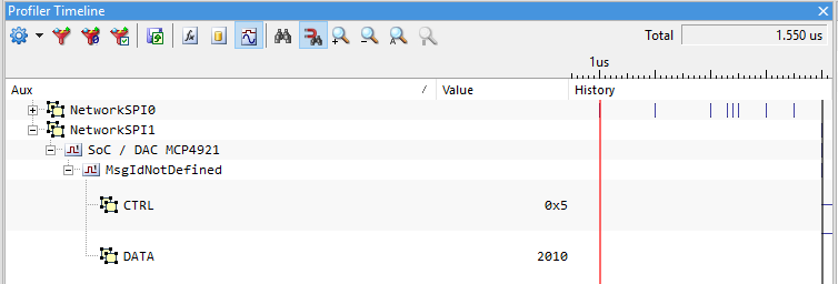
Let's start with simple decoding - all control bits ( A/B, BUF, GA, SHDN) will be shown as signal CTRL, data bits D0-D11 will be shown as signal DATA. For values shown in the table above, values will be:
CTRL = 0x6
DATA = 0x3CD
This we would like to see in winIDEA.
Decoder description starts with XML root element called spi:
<?xml version="1.0" encoding="UTF-8" ?> |
The next item is element declarations, which contains enum elements. The enum elements are identified with ID, and contain mappings between values and human readable names as item elements. In this example we only need to define names of signals. Values are assigned automatically and do not need to be specified:
<declarations> |
Once names of signals are defined, we have to define which bits from SPI message will be assigned to each of the signals. This can be done in sections
mosi and miso. As section names imply, they contain bits sent from master to slave and from slave to master respectively. In this example there is no response from slave device, so section miso is not defined. Since this example contains only unsigned integer values, element uint will be used as value description. See SPI message definition for more information about other available value formats. Description for decoding in this example is shown below:
<mosi> |
Attributes startBit and numBits define bits in SPI signal to be decoded as value. Attribute signalId defines name of signal in winIDEA analyzer. It must be specified with enum ID as declared in section declarations, double colon ('::)', and name of enum item. Example: SigId::DATA.
Element sigProps defines signal properties. Signal values are printed in hex by default, so decimal format must be specified explicitly.
Since BlueBox hardware supports several SPI analyzers, it makes sense to name each device. This can be done with elements master and slave:
<master name="SoC"/> |
Complete spi file with all information described above is shown below:
<?xml version="1.0" encoding="UTF-8" ?> |
Advanced SPI protocol description
This section will show some of the advanced features of TASKING SPI decoder. The previous example will be expanded to provide more fine grained description of SPI message.
Decoding of control bits
Signal CTRL from previous example provides information about control bits, but the state of each bit is visible only as a bit in hex value. To show bits in winIDEA analyzer as signals with name and value, the mapping between values and names must be provided in enum elements in section declarations, for example:
<declarations> |
As you can see the enum SigId with signal names now contains more items, and there are additional enums for mapping between values of signals and their human readable strings.
Section mosi is now defined as:
<uint startBit="0" numBits="1" signalId="SigId::DAC_SELECT"> |
Displaying float value
To see the DAC output voltage in winIDEA, additional signal with transformation and unit (Volts) can be defined:
<floatFromUint startBit="4" numBits="12" signalId="SigId::DATA_FLOAT"> |
Since signals DATA and DATA_FLOAT now decode the same bits, it is recommended to extract common information into section declarations:
<declarations> |
Now decoding can be written as:
<floatFromUint base='dataBits' signalId="SigId::DATA_FLOAT"> |
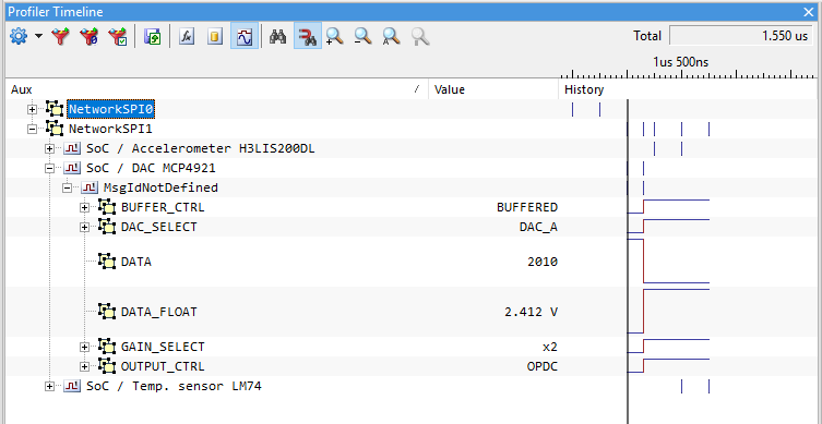
Complete .spi file and winIDEA view:
<?xml version="1.0" encoding="UTF-8" ?> |
As seen from the image, message ID is not defined in protocol description. This is perfectly valid, especially in simple cases like this one.
Conditional decoding and message IDs
This example shows decoding specification for more complex SPI signal of EEPROM NM93C66 (https://uk.rs-online.com/webdocs/002a/0900766b8002af95.pdf, pages 5, ...). For the purpose of SPI signal decoding, the following table can be used:
Instruction Set for the NM93C66
time à |
|||||
Instruction |
SB |
Op. Code |
Address |
Data |
Data Comments |
READ |
1 |
10 |
A7-A0 |
|
Reads data at specified address. |
WEN |
1 |
00 |
11xxxxxx |
|
Write enable must precede all programming modes. |
ERASE |
1 |
11 |
A7-A0 |
|
Erase selected register. |
WRITE |
1 |
01 |
A7-A0 |
D15-D0 |
Writes selected register. |
ERAL |
1 |
00 |
10xxxxxx |
|
Erases all registers. |
WRALL |
1 |
00 |
01xxxxxx |
D15-D0 |
Writes all registers. |
WDS |
1 |
00 |
00xxxxxx |
|
Disables all programming instructions. |
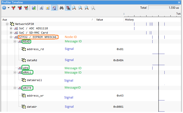
This section shows how to specify message decoding to get the following presentation in winIDEA.
As we can see from columns Op. Code and Address, the number of bits identifying Instruction is not fixed, but depends on Op. code. If Op. code is 00, then command is 4 bits long, otherwise it is 2 bits long. To decode this kind of signal, switch element can be used. It is similar to switch statement in C language with case and default sections. Additional attribute named var is specified in element uint. This attribute defines name of variable to be used for storing decoded uint value. This variable is later used in switch element:
<uint var="command" startBit="1" numBits="2"> |
The first uint element reads two bits of command and stores value into variable command. Then switch statement is used to decode additional bits according to value of the first two bits. Nested switch element reads also data value in case of command WRALL.
It also makes sense to show commands as different types of messages in winIDEA. To achieve this, command will be used as message ID. This can be done with element messageId:
<messageId var='command' enumId='Cmd' /> |
Attribute enumId is mandatory and defines enum element in section declarations, which is used for mapping of values to more human readable strings
<enum id="Cmd"> |
Complete .spi file:
<?xml version="1.0" encoding="UTF-8" ?> |
Specifiying the SPI protocol file in winIDEA
Once .spi files are written, winIDEA has to know how to associate these files with hardware port and SPI interface - chip select ID. This is done in winIDEA dialogs opened with menu Hardware / Options / FNet:
|
Open SPI1 tab (or SPI2) and enable SPI via Hardware / Options / FNet / ADIO. |

|
Add SPI description files (*.spi) with Add button |

SPI protocol analyzer modules (SP1, SP2) are by default disabled because they consume BANKS. When SP1 is enabled it consumes DIO BANK0. When SP2 is enabled it consumes DIO BANK2.

|
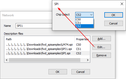
Select the chip. |

Chip Select is required. Click Edit in Network dialog. In SPI dialog and specify chip for each spi. file.
|
Chip Select is mandatory step also in the case of one CS. |

Single master, single slave SPI protocol configuration
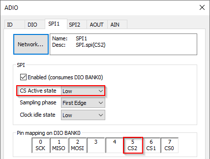
If you are using only one Slave/Chip Select you have to connect pins permanently to GND or to VCC Target (the same as I2C is supplied with) depending on the CS Active state:
|
Select Low CS Active state via Hardware / Options / FNet / ADIO / SPI. |
|
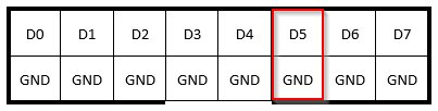
Connect with clip wire pin 5 CS2/D5 (or 6 CS1/D6 or 7 CS0/D7) on DIO BANK0 (or DIO BANK2) to GND. |
Example: BANK as specified in winIDEA or Digital connector of ADIO.
|
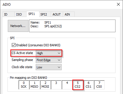
Select High CS Active state |
|
Connect with clip wire pin 5 CS2/D5 (or 6 CS1/D6 or 7 CS0/D7) on DIO BANK0 (or DIO BANK2) to VCC Target (the same as I2C is supplied with). |

Troubleshooting
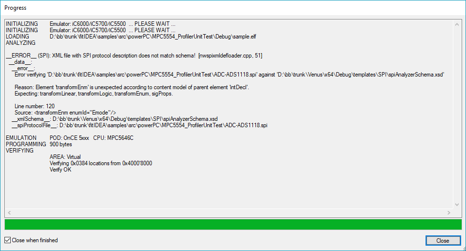
Syntax errors
Syntax errors in XML file and schema violations are reported during initialization phase in download dialog. It is recommended to have check-box Close when finished unchecked to see error messages.
Example
Runtime errors
Run-time errors occur during SPI signal decoding. These errors are visible in analyzer view, so it is possible to see when in time some error occurred.
Errors related to decoding of message ID
If there is an exception during decoding, then message ID is set to 0xDEC0DE, resembling word decode, and detailed error is given in place of value which decoding caused the error:

If message ID can not be decoded (for example there is no variable with name specified in messageId element), then message ID has value 0XBAD1D resembling words BAD ID.

Errors related to decoding of values (signals)
Message:
Bit range exceeds recorded data! (s=startB, n=numB, m=msgBits [0xssss_nnnn_mmmm])
Description:
Value is decoded from SPI signal based on attributes startBit and numBits of elements int, uint, floatFromInt or floatFromUint. If this position is larger than bit stream size, this error is reported. Values of attributes and recorded bit stream size are encoded in signal value as described in the error message. To resolve this error, check values of attributes and recorded bit stream size.
Message:
Database for this SPI node not found! (val=MOSI[63:32]MISO[31:0])
Description:
There is no SPI protocol description file defined for data received in this SPI node. The chip select ID in question is visible from tree element in analyzer shown as Node_<X>, where <X> means chip select number. Signal value shows the starting bits of SPI signal. Recorded signal may be longer or shorter than the number of bits shown.
Messages:
Variable from 'switch' element not defined! (val=ASCII var)
Variable from 'assign' element not defined! (val=ASCII var)
Description:
To resolve this error make sure, that the unknown variable is defined before the switch or assign statement in question. Define it in one of value decoding elements (int, uint, floatFromInt or floatFromUint) or assign element.
Note: Because of large amounts of data handled by winIDEA analyzer, memory must be used with care, so error reporting capabilities are limited. For this reason variable name is encoded in signal value as characters in ASCII encoding. Use Hex to ASCII converter (available also on the Web) to get variable name.