Connecting the BlueBox and the Target with Active Probe Parallel
In this topic:
Introduction
The Active Probe Parallel is connected to the Target via:
•two 30 and 40-pin ribbon cable adapters
•iC7 Active Probe Adapter
and the other side to the iC7max/iC5700 FNet port via the FNet cable.
Configurations steps

|
Connect the Active Probe's FNet cable to the BlueBox FNet port. |

|
Connect the ribbon cable adapters to the iC7 Active Probe Adapter. |

|
Connect the Active Probe Adapter to the Target. |

A white dot indicates pin one. Connectors also have a key and socket. Insert (and remove) the black connector parallel to the surface of the Target.

Power on the hardware
|
Power on the BlueBox. |
|
Power on the Target. |
When debugging is completed the hardware should be powered off in the reverse order.

Test the communication
By following these two simple steps, you can successfully verify communication with the BlueBox and eliminate the possibility of communication issues.
|
Go to Hardware | Debugger Hardware | Communication. |
|
Press Test. |
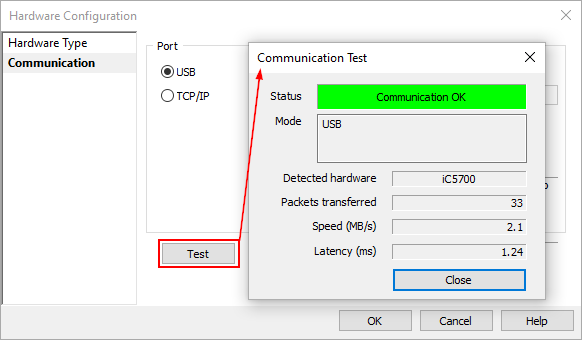
If the Communication Test Status displays Hardware not found , follow the Communication issues category in Knowledge Base.
Next step
•Create your first winIDEA IDE Workspace
More resources
•How to connect BlueBox Hardware - Video Tutorial
•Active Probe Parallel - Hardware User Manual