Perform SWO Calibration
In this topic:
•Using the Trace Line Calibration tool
•Using Logic analyzer or oscilloscope
•Clock determination from the SoC configuration
Introduction
This topic describes how to use the SWO Calibration which obtains the SWO clock frequency and the Prescaler (clock divider) value in a semi automated way.
Data Rate
The Data Rate setting relates to an amount of internal BlueBox clock cycles relative to one SWO bit. As the SWO uses a UART (Universal Asynchronous Receiver/Transmitter) protocol and hence the more time (cycles) per UART bit the more timing margin and hence error margin results.
•Fastest - Starts the calibration with the fastest possible SWO clock settings and results in the highest possible SWO bit rate (speed) but potentially at the price of the stability of long trace recordings. This should only be used if the device internal clock from which the SWO clock is derived is stable, e.g., derived from a crystal oscillator.
•Optimum (Recommended) - Optimum setting between speed and SWO baudrate error margin.
•Slow - Offers the highest SWO baudrate error margin at the expense of speed. Use this if the clock originates from an internal oscillator which varies widely over voltage and temperature.
|
SWO Calibration is available on the iC7pro/iC7max/iC5700 BlueBox only. |
Configuration steps
|
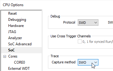
Make sure the SWO Trace Capture method is selected in Hardware | SoC Options | SoC. |

|
Run the application and make sure the SoC clock is set. |

The SoC should run until the clock initialization completes as the SWO clock can depend/vary based on it.
|
Stop the SoC. |

|
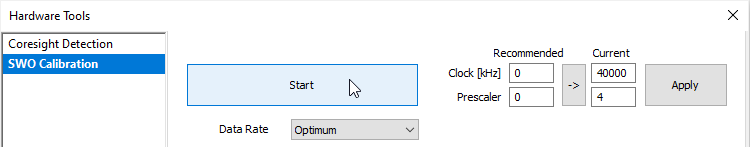
Select the Data Rate and start the SWO Calibration via Hardware | Tools | SWO Calibration. |

|
Once the calibration condition - Data Rate (Optimum, Fast, Slow) is changed a new debug session should be started. |
|
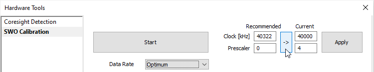
Copy the Recommended values to Current via the arrow button. |

|
Apply the Recommended values and transfer the results to Hardware | SoC Options | SoC | SWO. |

Note that changes will apply in the next session. It is recommended to save this configuration to the workspace (File | Save All).

|
Make sure winIDEA Debug Status is OFFLINE. |

Make sure that winIDEA is disconnected. If that is not the case, disconnect it via Debug | End Session.
|
Perform Reset Download. |

Other methods
If you are not be able to obtain the Prescaler and the Clock value by using SWO calibration tool, you can do it by one of the less commonly used methods:
•Using Trace Line Calibration tool
•Using Logic analyzer or oscilloscope
Using the Trace Line Calibration tool
Trace Line Calibration is usually used for identifying and configuring optimal settings of trace signals when using parallel trace. However, the tool can be also used to determine the SWO clock. This is especially useful when the SWO Calibration is not supported, for example on the iC5000 BlueBox.
|
Make sure the Parallel Trace Capture method is selected in Hardware | SoC Options | SoC. |
|
Run the application. |
Debug status must be RUN .
|
Start the Trace Line Calibration by pressing Start in Hardware | Tools | Trace Line Calibration. |
Wait for the result, the calibration might take a minute.
|
Multiply the value obtained from Measured trace clock by two. |
|
Configure Hardware | SoC Options | SoC. |
a)Select SWO as Trace Capture method.
b)Enter the calculated value into SWO | Clock.
|
Perform Reset or Download. |
The limitation of this method is when parallel trace is not exposed via the CoreSight 20-pin debug connector on the embedded target. In such case, use one of the next methods.
Using Logic analyzer or oscilloscope
Using the logic analyzer or oscilloscope, you can measure the SWO clock directly from the SWO pin.
|
Find the SWO pin on the target. |
|
Connect the probe to the pin and record the signal. |
|
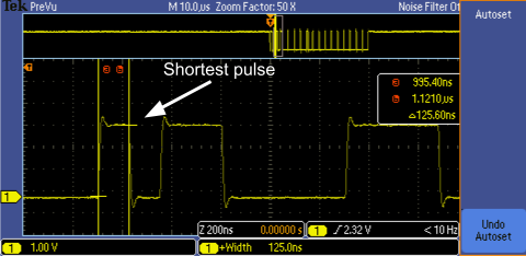
Find the shortest pulse in the record. |
|
Calculate the SWO clock frequency from the shortest measured period. |
It can be assumed that the width of this pulse is equal to one period of the signal. For greater reliability, these steps can be repeated several times.
|
Configure Hardware | SoC Options | SoC. |
c)Select SWO as Trace Capture method.
d)Enter the calculated value into SWO | Clock.
|
Perform Reset or Download. |
|
Your application needs to ensure that the trace components and the SWO pin are configured correctly. |
Clock determination from the SoC configuration
The last method is clock determination from the SoC configuration. If you decide to use this method, you must be familiar with the clocking infrastructure of your particular microcontroller. For more information, refer to the reference manual of your device.
|
Of all the above methods, this method is the least reliable, as some details can be missed quickly. |
