How to program TC2xx HSM
In this topic:
•Programming the TriCore application and the HSM code
Introduction
This topic describes a procedure of programming an HSM application through winIDEA on Infineon AURIX TC2xx devices.
The HSM (Hardware Security Module) is an optional module available on selected AURIX devices.
The HSM protection is configured in the User Configuration Block (UCB). UCBs serve as vital repositories of critical settings and configurations that drive the behavior and functionality of SoC features. They play a pivotal role in ensuring unmatched configurability. UCBs allow developers to define and configure crucial settings such as:
•Reset vector
•RAM initialization
•Hardware Security Module (HSM) configuration
•Logic Built-In Self-Test (LBIST)
•FLASH protection
•etc.
Through winIDEA, you can program an HSM application and configure the UCB (User Configuration Block) which is required to enable the HSM on your AURIX device.
Preventing device lock
•Devices or cores can be locked or hidden by the silicon vendor. Refer to Device/core is hidden or locked for more information.
•Read your AURIX device reference manual carefully
•Be cautious when debugging the HSM core: programming or erasing HSM-reserved FLASH sectors may lock the device.
•Wrong UCB data can permanently lock the device. Use winIDEA Demo Mode before FLASH programming to check if all UCB sectors contain correct data.
•The number of UCB writes is limited. Check your TriCore device documentation for exact limits.
•Uncheck the <UCB_device> box once UCB is programmed.
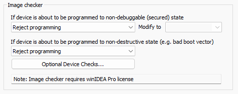
•Use the Image Checker during UCB or HSM code programming.
•HSM application programming and UCB configuration must be done carefully. Misconfiguration can lock the chip.
Requirements
•winIDEA 9.21.0 or newer
•iC7/iC5000/iC5700 BlueBox
oiC7: Infineon AGBT/SGBT Active Probe / Infineon DAP/DAPE Active Probe
oiC5: Infineon AGBT/SGBT Active Probe / Infineon DAP/DAPE Active Probe / 10-pin 1.27 mm Infineon DAP2 Wide Debug Adapter / 22-pin ERF8 DAP2 Debug Adapter
Configuration steps
The proper procedure to program your HSM application can be summarized in two steps:
1. Programming the TriCore application and the HSM code.
2. Enabling the HSM in the UCB.
Programming the TriCore application and the HSM code
1. Set the Image checker to Reject programming in Hardware | CPU Options | Debugging to prevent chip locking by misconfiguration.
2. Verify Program Files in Debug | Configure Session | SoC | Program Files.
For the regular TriCore application(s) and for the HSM.
3. Activate Tools | Demo mode and perform Debug | Download.
Your files must contain at least one valid boot mode header and valid HSM code before you proceed to enabling the HSM. With Demo mode you can see what is loaded into the target memory before you actually flash any code to your target.
4. Use Load Map in Debug | Show Load Map.
Inspect the contents of the BMHD locations (BMHD0 - BHMD3).
5. Disable Demo mode and perform a Debug | Download to program the code onto your target.
If the BMHD and HSM code are populated correctly you can program the code onto your target.
6. Check the validity of the programmed boot mode header
Make sure that the CPU0 boots correctly.
a. Disable presenting the CPU0 program counter by setting Hardware | CPU Options | Cores | CPU0 | Preset PC after stopped in init to Do not preset.
b. Reset the CPU via Debug | Reset and observe its reset vector.
|
Enabling the HSM without having a valid boot mode header programmed can permanently lock your chip! |

Enabling the HSM in the UCB
1. Enable UCB device in Hardware | Options | Programming.
|
The amount of writes to the UCB is limited. For the exact number of writes, refer to your AURIX device reference manual. Uncheck the UCB memory device once the UCB is programmed. |
2. Establish a Debug Session via Debug | Load Symbols Only.
3. Open the UCB plugin in View | AURIX | UCB. Double click on the UCB_HSMCOTP register. Change the values of the following registers:
•PROCONHSMCOTP_x - 0x01 or 0x781; Select the value and use it for all these registers.
•CONFIRMATION_x - UNLOCKED (0x43211234)
|
Recommended values for PROCONHSMCOTP_x during development are: 0x01 or 0x781. Other bits of this register should only be changed with extreme care, as you can lock the HSM flash, prevent start-up or disable debug access. Setting CONFIRMATION_x to CONFIRMED makes the whole UCB sector OTP protected from programming. |
After you click OK, the BlueBox programs UCB_HSMCOTP.
In case of any security violation, programming is rejected. This completes the configuration. After the power-on reset, the newly entered UCBs are read by the CPU and the HSM is started accordingly.
More resources
•HSM - Troubleshooting tips