Reset
This chapter explains setup for reset in initialization operation. Open Hardware | CPU Options | Reset.
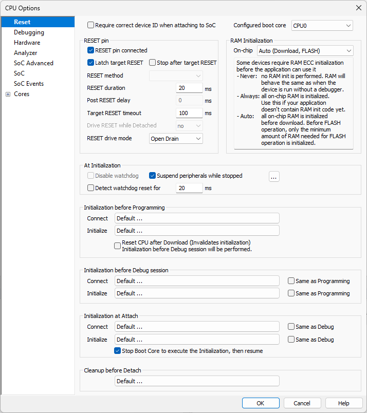
Require correct Device ID when attaching to SoC
Device ID is verified if it is present in the SoC (SFR/JSON) description. The following warnings are displayed in the Progress window:
Device ID |
Option Require correct... |
Warning |
|---|---|---|
Present and mismatched |
Checked |
ERROR SoC ID mismatch |
Unchecked |
WARNING SoC ID mismatch |
|
Present and matched |
Unchecked / checked |
SoC ID match OK |
Not present |
Unchecked / checked |
no progress output |
Configured boot core
Selected the boot core according to your application design.
|
Note that this option does not change the boot core on SoC, but only informs winIDEA about which core is being used as a boot core. |
RESET pin
RESET pin connected
Disable this option when the target reset line is not connected to the debug connector.
Latch target RESET
System reset line drivers on debugger side and target side are open collector. Either can pull it low. Assertion from target side can be missed by debugger if it is shorter than poll period of reset line. When the option is checked (default) the debugger hardware latches the reset line when being pulled low by target system. When polled next time the winIDEA acknowledges reset state. This yields a delay from when line is asserted by the target reset and the acknowledgement by winIDEA and potential restart of application. An example is an application where the CPU is periodically set into a power save mode and then woken up by an external reset circuit. In such case a delay introduced by the debugger would yield application not operating properly.
RESET method
Different reset methods are possible due to the problems arising from various wiring of the TRST (JTAG TAP reset), the SRST (system / CPU reset) and possible other reset signals (e.g. POR - power on reset) in the target system or inside the SoC (System on Chip). It is recommended that these otherwise independent signals are not connected together. However, sometimes they are tied together which can conflict with the debugger controlling the target microcontroller.
Proper reset wiring on debug connector should have independent TRST and SRST signals. Also their functionality should be independent – i.e. target debug module is reset when only TRST is activated while rest of the system continues running. Respectively debug module is left intact while only system is reset via SRST signal. This functionality depends on silicon and board design.
To keep the functionality needed for proper target initialization (explained further in text) other reset signals should be wired not to disrupt the described reset functionality. E.g. SRST if often replaced with POR signal on debug connector. Or sometimes both SRST and POR are connected. POR usually resets debug module like TRST does which is not expected by debug tools when putting system in reset state via SRST debug signal. Power-on reset should be one time event after powering the system on and should not repeat while power stays on.
Initialization steps
Following are the desired steps for proper initialization when debugger connects to the target (assuming target system is already powered on and debug connector is attached):
1.Target system is put in reset with activating SRST and not releasing it.
2.Target debug module is reset: TRST is activated for a moment and then released.
3.While system is still in reset a debug mechanism is set up to stop CPU execution when released from reset (also other debug settings are applied).
4.SRST is released and core doesn’t run. The target microcontroller is in known state and ready for next debug actions.
Several different reset methods are available:
Regular
(default, best debug experience)
This reset method assumes that TRST and SRST signals are separately connected from the microcontroller to the target debug connector. When the debug session is initialized a debug module is reset first via the TRST while the microcontroller is held in reset via the SRST thus preventing the core to run. The SRST is released after the debug module has been configured to stop the core after SRST is released.
SoC
(reasonable debug experience)
This is a method based on a mechanism implemented in the SoC (System on Chip) and should only be used if your target / microcontroller doesn't support Regular reset. First the microcontroller is reset via the SRST signal. Since the debug logic is not accessible when SRST is applied, the reset is released and the microcontroller starts executing the boot code, possibly the user application. As soon as the debug session is established, the microcontroller is reset via a debug reset command. Note that this reset command is SoC implementation specific, which means that the microcontroller might no longer be in a "fresh" state, you might notice traces of the executed code. Once the reset command is completed, the core will be stopped on its reset location.
|
Even though the core is reset and will be stopped on its reset location, some of the SFRs might be modified by the application which was running for a brief instant before the debug session was established. To avoid this effect, we advise you to place some code in the startup sequence, which will allow winIDEA to establish a debug session before any relevant code is executed. |

Stop and preset
This method should only be used if Regular or SoC reset is not possible. First the microcontroller is reset via the SRST signal. Since the debug logic is not accessible when SRST is applied, the reset is released and the microcontroller starts executing the boot code, possibly the user application. As soon as the debug session is initialized, the CPU is stopped. Note that some of the code will be already executed, which means that the microcontroller is no longer in a "fresh" state.
You can additionally select option Address (Preset PC after stopped in init) in Core specific options and specify the entry address to which you wish to preset the program counter.
|
The core and peripherals will not be reset, which means that you will see the traces of the executed code (changed core registers, special function registers). It is suggested to place some dummy code in the startup sequence, which will allow winIDEA to establish a debug session before any relevant code is executed. |
Set BP and wait
On some MCUs (most commonly seen on Cortex-A) the debug module is not accessible immediately after reset. In such case the MCU will automatically run after reset and debug tools need to wait until debug module becomes responsive. This method will attempt to set a breakpoint on the entry address (specified in the same tab) until debug logic is enabled by the application. Once debug module becomes available the breakpoint is set and once the MCU reaches this instruction, it will stop.
|
Since the application automatically runs after reset, it can happen that the instruction on the address, which you specified as an entry address, will already be executed by the time the breakpoint is set (once debug is responsive it takes some time to set a breakpoint). In this case the MCU will not stop, as the application already continued past the breakpoint. In such cases it is advised to create an infinite loop, which the MCU will perform until a breakpoint is set. This way you can make sure that the part of the application you wish to debug does not run before the debug session is established. |
Driving the SRST signal
The diagram below shows how the SRST line is driven when a reset is applied. Depending on your hardware, it is possible to adjust the timings to your need.

RESET Duration
Specify the length of the pulse on the SRST line. Note that in case of the Regular reset method, the debug logic is configured before the SRST is released, which makes the pulse a bit longer than specified with the RESET duration value.
Post RESET Delay
Specify the delay that winIDEA will wait after releasing the SRST line, before it tries to connect to the on-chip debug module and establish the debug session. This is particularly relevant when using SoC or Stop and preset reset methods.
Once the SRST is released, the on-chip debug module may need some time to become operational. This time can also depend on any additional reset circuitry on the target system. Keep in mind that the longer the delay, more of the code will be executed before the CPU is stopped or reset, so you should keep this setting as low as possible, while still giving the system time to stabilize.
Note that this delay is irrelevant for the Regular reset method, where the debug logic is configured before SRST is released. However, it may still be used to prevent user actions for the specified amount of time, in case you have additional hardware in your system, which needs more time to become fully operational.
Target RESET timeout
Specify the timeout that winIDEA will wait after releasing the SRST line, before it detects a high value. This timeout should be configured for targets that have a weak pull-up on the SRST line.
Drive RESET while Detached:
•no - BlueBox will not drive the RESET line. RESET will or will not occur depending on your application design.
•Low - BlueBox will pull down the RESET line. RESET will most likely not occur.
•High - BlueBox will pull up the RESET line. RESET will most likely occur.
RESET drive mode:
•Open-drain + Pull-up - RESET pin is configured as an open-drain output with pull-up. This is the preferred configuration. winIDEA can also detect when the external circuit on the target activates the RESET pin.
•Push-pull - RESET pin is configured as a push-pull output. Should be used with caution. The external circuit on the target must not actively drive the RESET pin, otherwise the debug adapter might get bricked.
•No drive - RESET pin will not be driven, except for the fixed internal pull-up resistor. The pin is configured as read-only, so external RESET requests will be detected. The Latch target RESET functionality is not changed.
•Open-drain - RESET pin is configured as an open-drain output without pull-up. winIDEA can also detect when the external circuit on the target activates the RESET pin. Pull-up on the RESET line should be implemented on the target.
Not all RESET drive modes are available in all configurations. For example, the No drive mode is not supported by iC5000.
|
Since the application automatically runs after reset, it can happen that the instruction on the address, which you specified as an entry address, will already be executed by the time the breakpoint is set (once debug is responsive it takes some time to set a breakpoint). In this case the MCU will not stop, as the application already continued past the breakpoint. In such cases it is advised to create an infinite loop, which the MCU will perform until a breakpoint is set. This way you can make sure that the part of the application you wish to debug does not run before the debug session is established. |
At Initialization
Disable watchdog
Checked by default on devices which have internal watchdog. If internal watchdog is not supported, this option is greyed out. Internal watchdog is disabled at Default and Custom initialization.
Suspend peripherals while stopped
When this option is checked, selected peripheral functions (e.g., timers) are stopped when the application is stopped. Peripheral functions can be selected via the button  . It is generally recommended that this option is checked, as this results in more predictable behavior of the debugged application when using these peripheral functions.
Refer to the microcontroller and architecture reference manuals for details.
|
This option, including its peripherals list, is available for specific microcontrollers only. If not supported, the option is greyed out. |
Detect Watchdog reset
winIDEA detects whether a reset has occurred within a configurable time period after the reset has been released. Watchdog detection is checked only after Reset/Program/Attach is performed from a disconnected debugger (Debug | End Session) and not on every Reset/Program/Attach.
The detection feature is disabled by default. However, you can specify the time period (in milliseconds) for checking the target's reset. The Progress window displays the results, e.g. Detecting watchdog activity for 1000 milliseconds. Reset asserted, probably watchdog activity.
Initialization
•Default settings should work for most cases. For Multi-core synchronization follow these instructions.
•If the default setting does not work in your case, follow the advise from Technical support.
•Detailed information on initialization sequence configuration may be found in the Initialization Sequence help topic.
Cleanup before Detach
This call point extends the emulation detach and is called on:
•Disconnect (Debug | End Session)
•Detach procedure (Debug | Detach)
By default the script runs all cores.