Memory
In this topic:
•Indicators in the Memory Window
Introduction
Memory window is best-suited for a raw view of the CPU memory. It allows you to:
•View memory contents
•Search memory for specific pattern
•Modify memory content
•Fill memory with specific pattern
•Dump memory contents to a file
|
Another way to check memory content is via Debug | Show Load Map, where you can precisely see to which memory the downloaded code is loaded. |
Memory Window colors locations that have changed in the previous action and indicate the location of the stack pointer when in range.
You can open a new Memory Window by clicking View | Debug | Memory | Create or clicking the Display Memory button  in the Debug Toolbar.
Real-time
Enable or disable real-time memory access.
|
It is recommended to use Watch Window Real-time Watch panes to inspect memory with minimum intrusion while the application is running. Find more information about Real-time Memory Access under Debug Option Memory Access and Update. |
Memory area selector
Shows which of the CPU's memory areas is currently displayed.
List Field
Is used to enter either the address or the symbol or anchor from which you wish to list the memory.
|
Drag-and-drop a register from Disassembly into Memory Window lists memory from register value. |
Address type field
Is used to select the type of the address specified (either HEX for Hexadecimal memory address, Symbol or Anchor). When Anchor is specified, the window is repositioned to the value of the expression, specified in Address, when the CPU stops.
Example: ":@SP" always shows the stack.
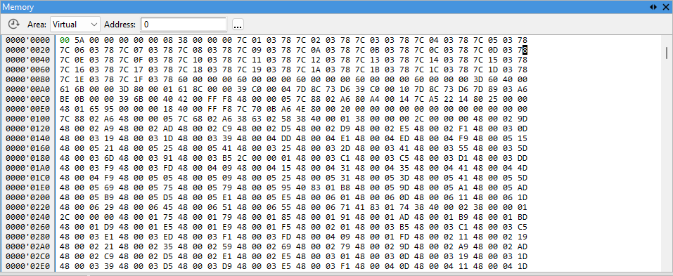
Address column
Displays the address of the first item in the numerical display area at the same line.
Numerical display area
Displays memory contents in binary, hexadecimal or signed or unsigned decimal or floating point format. Inaccessible regions (regions that are unavailable or the user defined them as inaccessible) and invalid regions (erased random-state flash regions) will be shown as ??.
|
Select Show Disassembly from the Memory Window's context menu to open the Disassembly Window from the current memory location. |
ASCII display area
Displays memory contents in ASCII format, if selected in the Display Mode window
Indicators in the Memory Window
Indicator |
Description |
|
|---|---|---|
78 |
Block caret |
Selected memory location. |
?? |
Question marks |
Memory read at a specific memory location failed. |
00 |
Green color |
Location of the stack pointer. |
33DD |
Red color |
Values changed after a previous read. |
Context menu
Display Mode - Open Display Mode dialog and configure the display of memory.
List From - Search for memory from address in decima/symbol or hexadecimal.
Fill - Modify memory content.
Show disassembly - Open Disassembly Window (if it is not already open) and update the content to that specific memory address.
Find - Search the memory space for specific memory content.
Save - Save memory content by address, size, format
Options - Customize colors and fonts for Memory Window.
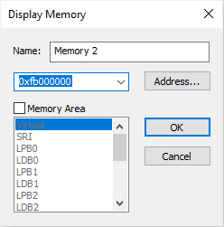
Opening Memory window
Multiple Memory Windows can be opened to view different regions of the memory space. Click View | Debug | Memory | Create and select the address you wish to inspect. Optionally select the memory area through which you wish to inspect it. Most common memory areas are:
•Virtual (as the CPU sees it)
•Physical (as seen on the bus)
The availability of the memory area depends on the CPU architecture.
Finding memory content
To search the memory space for specific memory content, select Find from the Memory window's Context menu, or hit CTRL+F.
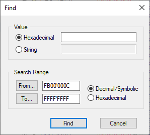
Value - With this function, a specified value can be found in the Memory Window. The value can be either hexadecimal or a string.
Search Range - The search range in which the value is to be searched for is entered here. The search range can be either hexadecimal (hexadecimal values are entered into the From… and To… fields), or decimal or symbolic. When Decimal/Symbolic is selected, the search range can be selected with the From… and To… buttons. Pressing one of those invokes the Symbol Browser.
Modifying memory content
Memory contents can be modified directly in either the ASCII display area or in the numerical display area.
|
Editing flash memory during debug session is disabled on some devices. |

|
If the memory does not change, the CPU might have problems with write access to that location. |
Fill dialog
When entering value in the ASCII display area or when using binary or hexadecimal display types, individual digits can be modified directly. In decimal (float and integer) display mode however, entering a new value automatically opens the Memory Fill dialog. This dialog can be also selected with Fill command from the Memory Window's Context menu or by pressing the Enter key.
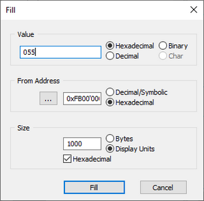
Value - Is used to enter new value. The value can be either hexadecimal, binary, decimal or a char.
|
The programmed pattern depends on the size of memory writes, which are specified with the size parameter, e.g. if memory accesses are byte-size, you can only program byte-size pattern. |
From Address - This is initially set to the address that was selected at the time the dialog opened, and can also be changed to some other memory location.
Number of Bytes / Display units - Is used to determine how many locations will be filled with the specified value.
The Bytes/Display Units setting should be set as follows:
•Bytes option should be selected to fill a certain number of consecutive bytes,
•Display Units option should be selected to fill a certain number of consecutive in the format that is currently displayed. (Example: if you display 4 byte floats and wish to set ten consecutive floats to value 1.0).
|
This selection specifies the size of memory access (if available). |
Display configuration
Display of the Memory Window can be configured through Display Mode option in the context menu by right-clicking within window.
Display Format - Determines the number format shown in the numerical display area.
Display Unit Size - This setting determines how many bytes will be grouped to form a value in the numerical display area.
Example: If the display type is set to 'Signed Decimal' and display unit size to '2 bytes' the values shown will range from -32768 to 32767. For float display type unit sizes of 4 and 8 are available, for all other display types sizes of 1, 2 and 4 bytes can be us.
Organization - When grouping several bytes, their ordering inside the group can be specified either to Low Byte First (little endian) or High Byte First (big endian).
Example:
Memory Address |
0 |
1 |
|---|---|---|
Data |
0xAA |
0xBB |
Low Byte First (little endian): WORD value is 0xBBAA
High Byte First (big endian): WORD value is 0xAABB
Character Display - Show ASCII display in addition to the numeral display specified by the Display Format.
|
The Memory Window always aligns itself according to display unit size setting. (If 4 bytes are selected, the window will align itself on a 4-byte boundary). |
Saving memory content
A region of memory can be saved to a binary disk file by selecting the Save command from the Memory window's Context menu.
Address - Determines the start address from which the memory will be saved. The range of memory to be saved can be defined providing the end address of the range or by specifying its size.
To - Determines the end address of the memory range that will be saved.
Size - Determines how many bytes or current display units will be saved. If you specify the size in hexadecimal format, make sure the 'Hexadecimal' option is checked.
File - Determines the file to which the memory will be saved.
Format - Defines the format in which the file will be saved. Note that winIDEA always uses Extended Linear Address Record to save Intel Hex.
|
While saving to Motorola and HEX file formats only valid memory contents will be saved. Some FLASH devices produce random state when the regions are erased. Such regions are considered not valid. When saving to binary format, whole content will be saved regardless. |
To configure colors and fonts, right-click in the window and select Options from the context menu.