Renesas E20/E2 Emulator
In this topic:
Introduction
The Renesas E20/E2 Emulator, when used with winIDEA, provides flash programming and basic debug functionality for Renesas microcontrollers. It's supported for the RH850 and RL78 microcontroller family and enables standard run-control debugging via the on-chip debug interface.
For systems that require advanced trace, timing analysis, or multi-core debugging, a TASKING BlueBox is required.
Requirements
To debug Renesas devices with winIDEA and an E-Series debugger, the following components are required:
•winIDEA 9.21.393 and newer (see the Download page)
•Renesas E-Series USB Driver
•Renesas E2/E20 Emulator
Supported families
The following Renesas device families are supported with the E-Series debuggers in winIDEA:
•RL78/D1A
•RL78/F12
•RL78/F13
•RL78/F14
•RL78/G13
•RL78/G14
•RL78/L12
•RL78 G23
•RL78 F23/24 (supported only via Renesas E20/E2 Emulator)
•RH850G3
•RH850G4
|
You must provide Renesas device file (.DVF) and copy to: <winIDEA install directory>/Renesas/devicefiles/ |
Features
•1-wire Serial (RL78)
•LPD 1-Wire, LPC 4-Wire (RH850)
•Basic debug control (Reset, Download, Stop, Run…)
•Flash programming
•Software and hardware breakpoints
•Power supply-to-target functionality
Getting started
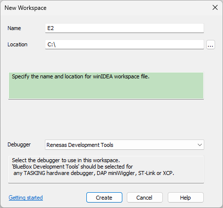
1. Create a new workspace in winIDEA in File | Workspace | New Workspace and select Renesas Development Tools.
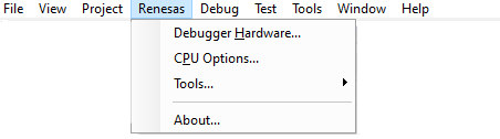
2. Configure setting via Renesas menu.
After creating a new workspace and selecting Renesas Development Tools, the Renesas menu appears in the main winIDEA toolbar.
3. Debug
4. Disconnect via Debug | End Session.
Settings
After creating a new workspace and selecting Renesas Development Tools, Renesas menu appears in the main winIDEA toolbar.
Debugger Hardware - Communication settings.
CPU Options
VDD Mode - Configure how the target board is powered.
•If target is powered from external source select VDD Target. E2 can provide power to target board (check E2 User Manual for limitations) by selecting “VDD E2 5V” or “VDD E2 3V”. Make sure to select compatible voltage level.
Debug interface - Communication method with target MCU. LPD 1-Wire and LPC 4-Wire can be selected.
LPD Mode Debug Speed - The LPD clock frequency in kHz (4-pin mode) or baud rate in kbps (1-pin mode). Set to 0 for default values.
Oscillator Frequency - Frequency (kHz) input as the main clock (EXTAL/XTAL).
PLL Multiplication Ratio - Set to 0 for no multiplication.
Security ID - Enter per byte security code. This will be used to establish debug connection to secured target.

|
On RL78 devices if current device Security ID code is not known, use option Erase Flash Before Next ID Check. |

Tools
Info - Provides useful information when troubleshooting debug chain issues. Some information can only be acquired after connection to the target device is established.
E2/E20 Self Check Program - Utility can be used to run self-check test of the connected E2/E20. See User’s Manual available on www.renesas.com. Utility can only be started when winIDEA is disconnected from emulator. To disconnect use Debug | End Session.