Target power control using BlueBox & ADIO
In this topic:
•Configuration steps for ADIO Add-on module
•Configuration steps for mDIO module
Introduction
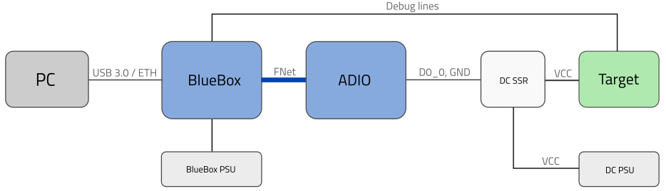
This topic explains how to utilize a solid state relay in combination with BlueBox and its accessories to gain control of the connected target's power source. The Python script can be used to control the power state of a connected embedded target. It is useful when the power-cycle of the target device is needed.
Requirements
•winIDEA
•BlueBox
•SSR - Solid state relay
•Power control pin which controls the SSR input side of the relay:
oOutput from ADIO Add-on module or
oBlueBox mDIO module
Applications
If you would like to toggle the target's power supply adapter which is powered from mains voltage, AC solid state relay should be used. If the solid state relay is not galvanically isolated, risk of damaging the power control pin by target is possible. Also, if the power control pin does not satisfy input specification of solid state relay, risk of damaging power control pin is still possible.
When the target is powered through a DC power supply (e.g. 3.3V, 5V, 12V, 24V), a DC solid state relay should be used. If the solid state relay is not galvanically isolated, risk of damaging the power control pin by target is possible. Also, if the power control pin does not satisfy input specification of solid state relay, risk of damaging power control pin is still possible.
Power control pin
To control the relay, a digital pin is required which will control the power of SSR. Usage of ADIO or mDIO module is suggested.
Configuration steps for ADIO Add-on module
Use the ADIO to control the power of a currently connected target.
|
Connect... |

•ADIO to the BlueBox via the FNet cable;
•Target to the SSR relay output according to following schemas:
|
|
AC Application |
DC Application |

|
Connect one channel from ADIO (e.g. D0_0) to the solid state relay input side: |

•If a solid state relay supports 3.3V input drive, connect it to any ADIO bank.
•In case, where a solid state relay needs a 5V input drive, make sure that it is connected to ADIO bank 2 or 3 (other banks support up to 3.3V levels).
|
Make sure the Grounding wire is connected. |

|
Provide Network description and configure ADIO. |

|
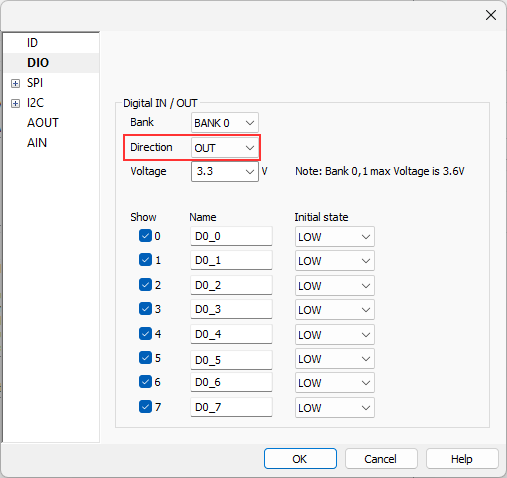
Configure fields according to your connected setup in the DIO page. |

Make sure that Direction is set to OUT.
|
Open View / HIL Monitor / View. |

|
Start a Debug session. |

|
Toggle ADIO channel which is wired to the SSR by changing Value on HIGH / LOW. |

Solid state relay should be turned on / off, depending on the value set. If you have the target connected to solid state relay output terminals, target should also be powered on / off, depending on the Value of ADIO output pin.
Configuration steps for mDIO module
Use the mDIO module (Active Probes, iC7mini, iC7pro and iC7max) to control the power of the currently connected embedded target.
|
Connect... |
•ADIO to the BlueBox via the FNet cable;
•Target to the SSR relay output according to following schemas:
|
|
AC Application |
DC Application |
|
Connect one channel from ADIO (e.g. D0_0) to the solid state relay input side: |
•If a solid state relay supports 3.3V input drive, connect it to any ADIO bank.
•In case, where a solid state relay needs a 5V input drive, make sure that it is connected to ADIO bank 2 or 3 (other banks support up to 3.3V levels).
|
Make sure the Grounding wire is connected. |
|
Provide Network description and configure ADIO. |
|
Configure fields according to your connected setup in the DIO page. |
Make sure that Direction is set to OUT.
|
Open View / HIL Monitor / View. |
|
Start a Debug session. |
|
Toggle ADIO channel which is wired to the SSR by changing Value on HIGH / LOW. |
Solid state relay should be turned on / off, depending on the value set. If you have the target connected to solid state relay output terminals, target should also be powered on / off, depending on the Value of ADIO output pin.
Python script example
Download and unzip the script example via the link: powerCycle.7z
Follow these steps to run the script in winIDEA:
|
Modify the attached script according to the required configuration. |
|
Save it in the same folder as winIDEA workspace. |
|
Connect solid state relay to ADIO the same way as described in the Python script configuration. |
|
Start a Debug session. |
|
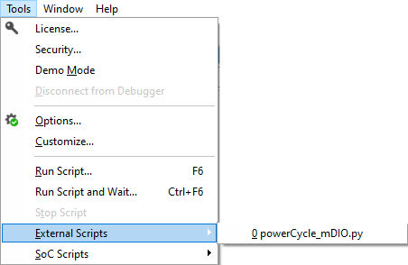
Select your Python script in Tools / External Scripts. |
|
To see if your selected solid state relay is SSR used in this example with ADIO please refer to the User Manual. SSR used in this example: •AC Relay example 528-6210BXXTZB-DC3 •DC Relay example 874-84137750 |
More resources
•DIO