Configuring MCDS and MCX for Time Stamp Generation
In this topic:
Introduction
By default, the MCDS does not generate time stamp messages. To include time stamp information in trace records, you must configure both MCDS and MCX.
For background information on time stamping concepts, refer to the topic Multi-Core Cross Connect (MCX).
Time stamps are implemented at the CPU (MCDS) tick level, meaning each time stamp corresponds to a CPU tick. To obtain accurate time data, you must determine the MCDS tick period.
|
This method relies on the assumption that the CPU clock doesn’t change during the active trace session. Time cannot be measured properly when tracing program code is changing the CPU clock. |

Configuration steps
1. In the MCDS configuration, enable Time Stamps.
a.Set Assume source to be to tsu_rel.
b.Keep default TSUPRSCL set to 1.
oValue of 1 triggers the tsu_tc_trig output every second reference clock cycle.
oIncreasing the value yields higher time resolution.
c.Reference clock set to Main PLL.
2. Determine and enter the MCDS Cycle Duration.
a.In the AURIX/Clocks plugin, read out the MCDS cycle duration.
b.Open Hardware CPU | Options | Analyzer.
c.In the Cycle duration field, enter the MCDS cycle duration value obtained in the previous step.
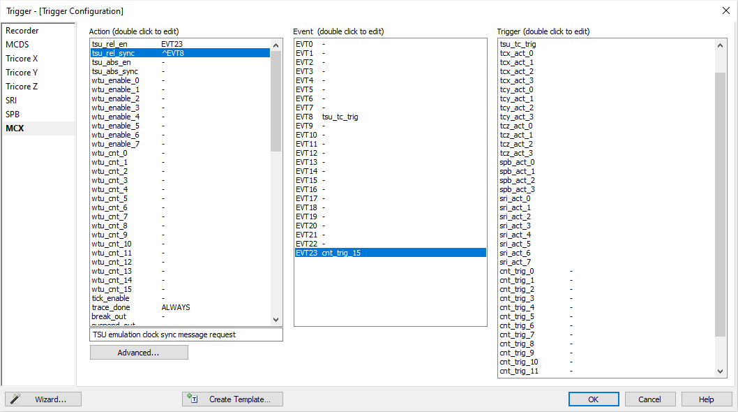
3. Configure MCX for time stamp generation.
The MCX must also be configured to generate time stamps when using trace Trigger/Qualifier operation modes. The easiest way to do this is by using the Trace Wizard.
a.Launch the Trace Wizard and configure a basic trigger, for example:
oTrigger immediately
oRecord Program Flow
b. The wizard will automatically configure the necessary MCX time stamp generation settings, regardless of specific trigger or qualifier options.
Component |
Configuration |
|---|---|
Event |
EVT8 → tsu_tc_trig EVT23 → cnt_trig_15 |
Action |
tsu_rel_en → on EVT23 Event State tsu_rel_sync → on EVT8 Event Edge trace_done → ALWAYS (records all trace data from the start) |
4. Verify Cycle duration in Hardware | CPU Options | Analyzer.
Before using trace time stamps, ensure that the Cycle duration in
|
The trace time stamp information is implemented on a CPU tick level only. You need to find out the CPU cycle period of your target application and enter that value in the dialog. This type of time stamps doesn’t provide accurate trace time information for applications where the microcontroller frequency is not constant during the trace session. |
More resources
•Multi-Core Cross Connect (MCX)