Converters
In this topic:
•Cross Table iC7 / Active Probe Adapters and Converters
•Texas Instruments 60-pin MIPI Converter
•MPC 14-pin JTAG to MPC Samtec 34-pin Converter
•50-pin ERF8 MPC5xxx Nexus Converter
•DAP 10-pin 1.27mm to HSTCU (USB-C) Converter
•MEDC17 DAP 10-pin 1.27mm Converter
•10-pin DAP2 to 22-pin ERF8 DAP2
•14-pin 2.54 mm RH850 to RH850 Aurora 46-pin
If your Target connector and iC7 / Active Probe Adapter do not align, and you are unable to locate another compatible iC7 / Active Probe Adapter, you may consider ordering a Converter designed to adapt the signals and pins to fit your embedded target and iC7 / Active Probe Adapter.

Block diagrams showing how BlueBox Hardware is connected
Cross Table iC7 / Active Probe Adapters and Converters
Below you can find a table with Converters and suitable iC7 / Active Probe Adapters.
iC7 / Active Probe Adapters |
|||||||
|---|---|---|---|---|---|---|---|
IC70111 |
IC70115 |
IC70150 |
IC70152 |
IC70163 |
IC70176 |
||
Converters |
|
||||||
IAMIC38MIPI60TMS570 |
|
|
|
|
|
|
|
IAMPCPIN14SAM34 |
|
|
|
|
|
|
|
IAMIC38SAM50MPC |
|
|
|
|
|
|
|
IADAP10-HSTCU |
|
|
|
|
|
|
|
IADAP10MEDC17 |
|
|
|
|
|
|
|
IA10PINDAP22PINSAM |
|
|
|
|
|
|
|
IAPIN14RH850SAM46 |
|
|
|
|
|
|
|
Texas Instruments 60-pin MIPI Converter
|

Embedded targets based on Texas Instruments (TI) TMS570 microcontroller can feature Texas Instruments 60-pin MIPI target debug connector with the TI proprietary pinout. A converter connecting at the end of the Mictor 38-pin ARM Parallel 16-bit Debug Adapter is available for Texas Instruments 60-pin MIPI pinout and must be ordered separately.
|
The iC5000 and the iC5700 can trace up to 16 trace data lines. For this reason the target microcontroller has to be configured for 16-bit trace port operation even if the target features 60-pin MIPI connector with 32 data trace lines connected. |

|
Signal naming in the documentation uses target signal names and not the ones from the MIPI standard. Refer to ‘MIPI Alliance Recommendation for Debug and Trace Connectors’ and ‘ARM Target Interface Connections’ documentation for more information about signal names and their functions. |
The converter connects to the target via a 60-pin MIPI connector, for example Samtec QTH-030-01-L-D-A. A target should feature a matching part, for example Samtec QSH-030-01-L-D-A.
|
This converter is used only in conjunction with the 38-pin Mictor ARM Parallel 16-bit Debug Adapter (Ordering code IC50115). |
The following pinout is valid on the target side:
Signal Direction |
Signal Description |
Signal |
Pin |
Pin |
Signal |
Signal Description |
Signal Direction |
|---|---|---|---|---|---|---|---|
I |
Reference Voltage |
Vref |
1 |
2 |
TMS |
JTAG |
O |
O |
JTAG |
TCK |
3 |
4 |
TDO |
JTAG |
I |
O |
JTAG |
TDI |
5 |
6 |
nRESET |
Reset |
O |
O |
Return TCK |
RTCK |
7 |
8 |
nTRST |
JTAG Pull down |
O |
O |
JTAG Pull up |
nTRST |
9 |
10 |
NC |
Not Connected |
|
|
Not Connected |
NC |
11 |
12 |
NC |
Not Connected |
|
I |
Trace Clock |
TRACECLK |
13 |
14 |
NC |
Not Connected |
|
|
Not Connected |
NC |
15 |
16 |
GND |
Ground |
|
I |
Trace Data |
TRACECTL |
17 |
18 |
NC |
Not Connected |
|
I |
Trace Data |
TRACEDATA0 |
19 |
20 |
NC |
Not Connected |
|
I |
Trace Data |
TRACEDATA1 |
21 |
22 |
NC |
Not Connected |
|
I |
Trace Data |
TRACEDATA2 |
23 |
24 |
NC |
Not Connected |
|
I |
Trace Data |
TRACEDATA3 |
25 |
26 |
NC |
Not Connected |
|
I |
Trace Data |
TRACEDATA4 |
27 |
28 |
NC |
Not Connected |
|
I |
Trace Data |
TRACEDATA5 |
29 |
30 |
NC |
Not Connected |
|
I |
Trace Data |
TRACEDATA6 |
31 |
32 |
NC |
Not Connected |
|
I |
Trace Data |
TRACEDATA7 |
33 |
34 |
NC |
Not Connected |
|
I |
Trace Data |
TRACEDATA8 |
35 |
36 |
NC |
Not Connected |
|
I |
Trace Data |
TRACEDATA9 |
37 |
38 |
NC |
Not Connected |
|
I |
Trace Data |
TRACEDATA10 |
39 |
40 |
NC |
Not Connected |
|
I |
Trace Data |
TRACEDATA11 |
41 |
42 |
NC |
Not Connected |
|
I |
Trace Data |
TRACEDATA12 |
43 |
44 |
NC |
Not Connected |
|
I |
Trace Data |
TRACEDATA13 |
45 |
46 |
NC |
Not Connected |
|
I |
Trace Data |
TRACEDATA14 |
47 |
48 |
NC |
Not Connected |
|
I |
Trace Data |
TRACEDATA15 |
49 |
50 |
NC |
Not Connected |
|
|
Not Connected |
NC |
51 |
52 |
NC |
Not Connected |
|
|
Not Connected |
NC |
53 |
54 |
NC |
Not Connected |
|
|
Not Connected |
NC |
55 |
56 |
NC |
Not Connected |
|
|
Ground |
GND |
57 |
58 |
GND |
Ground |
|
|
Not Connected |
NC |
59 |
60 |
NC |
Not Connected |
|
60-pin MIPI pinout
Blue colored signals are trace signals.
Signal Direction is described from the BlueBox perspective.
MPC 14-pin JTAG to MPC Samtec 34-pin Converter
|

This converter connects between the 14-pin 2.54mm MPC5xxx Debug Adapter (Ordering code IC50150) and the MPC5xxx/SPC5 target featuring a 34-pin Samtec ERF8 connector exposing Aurora trace interface.
The following pinout is valid on the target side:
Signal Direction |
Signal Description |
Signal |
Pin |
Pin |
Signal |
Signal Description |
Signal Direction |
|---|---|---|---|---|---|---|---|
|
Not Connected |
NC |
1 |
2 |
Vref |
Reference Voltage |
I |
|
Not Connected |
NC |
3 |
4 |
TCK |
JTAG |
O |
|
Ground |
GND |
5 |
6 |
TMS |
JTAG |
O |
|
Not Connected |
NC |
7 |
8 |
TDI |
JTAG |
O |
|
Not Connected |
NC |
9 |
10 |
TDO |
JTAG |
I |
|
Ground |
GND |
11 |
12 |
nJCOMP |
JTAG TRST (optional) |
O |
|
Not Connected |
NC |
13 |
14 |
NC |
Not Connected |
|
|
Not Connected |
NC |
15 |
16 |
~EVTI0 |
Nexus Event Input |
O (not used) |
|
Ground |
GND |
17 |
18 |
Not Connected |
NC |
|
|
Not Connected |
NC |
19 |
20 |
nPORESET |
Power On Reset |
O |
|
Not Connected |
NC |
21 |
22 |
nRESET |
Reset |
IO |
|
Ground |
GND |
23 |
24 |
GND |
Ground |
|
|
Not Connected |
NC |
25 |
26 |
Not Connected |
NC |
O |
|
Not Connected |
NC |
27 |
28 |
Not Connected |
NC |
O |
|
Ground |
GND |
29 |
30 |
GND |
Ground |
|
|
Not Connected |
NC |
31 |
32 |
NC |
Not Connected |
|
|
Not Connected |
NC |
33 |
34 |
NC |
Not Connected |
|
34-pin MPC Samtec pinout
Blue colored signals are parallel trace signals.
Signal Direction is described from the BlueBox perspective.
Only debugging (no trace) is possible through this converter. The converter must be ordered separately.
|
When initially connecting the BlueBox to a target, ensure the debug adapter pinout matches the Target connector to avoid potential hardware failure. |
|
Make sure this adapter fits on your target connector - check Cross Table. |
|
Refer to Hardware Setup and Configuration Tutorial for more information on how to connect the hardware. |
50-pin ERF8 MPC5xxx Nexus Converter
|

Some targets based on NXP MPC5xxx / ST SPC5 family can feature a 50-pin Samtec ERF8 connector for the Nexus debug interface instead of the popular 38-pin Mictor connector. In this case use and connect the converter to the target first and then connect the 38-pin Mictor MPC5xxx Nexus 16-bit Debug Adapter to the converter.
|
It has been noticed that the 50-pin Samtec ERF8 target connector may not always provide good mechanical stability in a vertical direction which can in worst case yield an unreliable debug connection. Special care must be taken when connecting this debug adapter to the target to prevent potential connection problems. |
|
When initially connecting the BlueBox to a target, ensure the debug adapter pinout matches the Target connector to avoid potential hardware failure. |
The converter connects to the target via a 50-pin Samtec ERM8 connector, Samtec ERM8-025-01-L-D-EM2-TR. A target should feature a matching part, for example Samtec ERF8-025-05.0-L-DV.
|
Make sure this adapter fits on your target connector - check Cross Table. |
|
Refer to Hardware Setup and Configuration Tutorial for more information on how to connect the hardware. |
The following pinout is valid on the target side:
Signal Direction |
Signal Description |
Signal |
Pin |
Pin |
Signal |
Signal Description |
Signal Direction |
|---|---|---|---|---|---|---|---|
I |
Message Data Clock |
MSEO0 |
1 |
2 |
Vref |
Reference Voltage |
I |
I |
Message Data Clock |
MSEO1 |
3 |
4 |
TCK |
JTAG |
O |
|
Ground |
GND |
5 |
6 |
TMS |
JTAG |
O |
I |
Message Data Outputs |
MDO0 |
7 |
8 |
TDI |
JTAG |
O |
I |
Message Data Outputs |
MDO1 |
9 |
10 |
TDO |
JTAG |
I |
|
Ground |
GND |
11 |
12 |
nJCOMP |
JTAG TRST (optional) |
O |
I |
Message Data Outputs |
MDO2 |
13 |
14 |
NC |
Not Connected |
|
I |
Message Data Outputs |
MDO3 |
15 |
16 |
EVTI |
Nexus Event Input |
O |
|
Ground |
GND |
17 |
18 |
EVTO |
Nexus Event Output |
I |
I |
Message Data Clock |
MCKO |
19 |
20 |
nRESET |
Reset |
O |
I |
Message Data Outputs |
MDO4 |
21 |
22 |
NC |
Not Connected |
O |
|
Ground |
GND |
23 |
24 |
GND |
Ground |
|
I |
Message Data Outputs |
MDO5 |
25 |
26 |
NC |
Not Connected |
|
I |
Message Data Outputs |
MDO6 |
27 |
28 |
NC |
Not Connected |
|
|
Ground |
GND |
29 |
30 |
GND |
Ground |
|
I |
Message Data Outputs |
MDO7 |
31 |
32 |
NC |
Not Connected |
|
I |
Message Data Outputs |
MDO8 |
33 |
34 |
NC |
Not Connected |
|
|
Ground |
GND |
35 |
36 |
GND |
Ground |
|
I |
Message Data Outputs |
MDO9 |
37 |
38 |
NC |
Not Connected |
|
I |
Message Data Outputs |
MDO10 |
39 |
40 |
NC |
Not Connected |
|
|
Ground |
GND |
41 |
42 |
GND |
Ground |
|
I |
Message Data Outputs |
MDO11 |
43 |
44 |
MDO13 |
Message Data Outputs |
I |
I |
Message Data Outputs |
MDO12 |
45 |
46 |
MDO14 |
Message Data Outputs |
I |
|
Ground |
GND |
47 |
48 |
GND |
Ground |
|
I |
Message Data Outputs |
MDO15 |
49 |
50 |
NC |
Not Connected |
|
50-pin Samtec ERF8 MPC5xxx Nexus target pinout
Blue colored signals are trace signals.
Signal Direction is described from the BlueBox perspective.
DAP 10-pin 1.27mm to HSTCU (USB-C) Converter
|

This converter is used to connect via 10-pin 1.27mm Infineon DAP2 Wide Debug Adapter (Ordering code IC50163-2) or Infineon DAP/DAPE II Active Probe to the USB-C target debug connector. The converter must be ordered separately.
|
When attaching this converter to the Active Probe, make sure its marking A and marking B is aligned and matches with the markings on the Active Probe connector. |
The following pinout is valid on the target side:
Signal Direction |
Signal Description |
Signal |
Pin |
Pin |
Signal |
Signal Description |
Signal Direction |
|---|---|---|---|---|---|---|---|
|
Ground |
GND |
A1 |
B12 |
NC |
Not Connected |
|
|
Not Connected |
NC |
A2 |
B11 |
NC |
Not Connected |
|
|
Not Connected |
NC |
A3 |
B10 |
NC |
Not Connected |
|
|
Not Connected |
NC |
A4 |
B9 |
NC |
Not Connected |
|
IO |
Target Reset Pin |
nRESET |
A5 |
B8 |
DAP1 |
DAP Data |
I |
IO |
Optional 2nd DAP data |
DAP2 |
A6 |
B7 |
nTRST* |
JTAG |
|
IO |
Optional 3rd DAP data |
DAP3 |
A7 |
B6 |
NC |
Not Connected |
|
O |
DAP Clock |
DAP0 |
A8 |
B5 |
Vref |
Reference Voltage |
I |
|
Not Connected |
NC |
A9 |
B4 |
NC |
Not Connected |
|
|
Not Connected |
NC |
A10 |
B3 |
NC |
Not Connected |
|
|
Not Connected |
NC |
A11 |
B2 |
NC |
Not Connected |
|
|
Ground |
GND |
A12 |
B1 |
GND |
Ground |
|
USB-C pinout
Signal Direction is described from the BlueBox perspective.
* Permanently pulled-up.
|
When initially connecting the BlueBox to a target, ensure the debug adapter pinout matches the Target connector to avoid potential hardware failure. |
MEDC17 DAP 10-pin 1.27mm Converter
|

The MEDC17 converter and the pinout have been defined by Bosch. The converter is connected at the end of the 10-pin 1.27mm Infineon DAP2 Wide D. Adapter (Ordering code IC50163-2) or Infineon DAP/DAPE II Active Probe acting as a pinout converter and is available for TriCore targets featuring the MEDC17 10-pin 1.27mm target debug connector. The adapter must be ordered separately.
The following pinout is valid on the target side:
Signal Direction |
Signal Description |
Signal |
Pin |
Pin |
Signal |
Signal Description |
Signal Direction |
|---|---|---|---|---|---|---|---|
|
|
|
1 |
2 |
|
|
|
|
Ground |
GND |
3 |
4 |
DAP0 |
DAP clock |
O |
I/O |
DAP Data pin |
DAP1 |
5 |
6 |
|
|
|
I/O |
Power on Reset |
nRESET |
7 |
8 |
nTRST/DAPEN |
Optional 3rd Data pin |
I/O |
I/O |
Reference Voltage |
Vref |
9 |
10 |
DAP2 |
Optional 2nd Data pin |
I/O |
10-pin MEDC17 target pinout
Signal Direction is described from the BlueBox perspective.
|
The pin next to the alignment pin is pin 10 and not pin 1! Pin is marked with a number 1 directly on the converter target connector. |
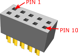 |
The converter connects to the target via a 10-pin 1.27mm connector, Samtec SFM-105-02-L-D-A. A target should feature a matching part, for example Samtec TFM-105-02-L-D.
10-pin DAP2 to 22-pin ERF8 DAP2
|

A converter connecting at the end of the 10-pin 1.27 mm DAP debug cable is available for Infineon 22-pin ERF8 AURIX pinout. This converter must be ordered separately.
The following pinout is valid on the target side:
Signal Direction |
Signal Description |
Signal |
Pin |
Pin |
Signal |
Signal Description |
Signal Direction |
|---|---|---|---|---|---|---|---|
|
Not Connected |
NC |
1 |
2 |
Vref |
Reference Voltage |
I |
|
Not Connected |
NC |
3 |
4 |
DAP0 |
DAP Clock |
O |
|
Ground |
GND |
5 |
6 |
DAP1 |
DAP Data pin |
I/O |
|
Not Connected |
NC |
7 |
8 |
NC |
Not Connected |
|
|
Not Connected |
NC |
9 |
10 |
DAP2 |
Optional 2nd Data pin |
I/O |
|
Ground |
GND |
11 |
12 |
nTRST |
JTAG |
O |
|
Not Connected |
NC |
13 |
14 |
NC |
Not Connected |
|
|
Not Connected |
NC |
15 |
16 |
NC |
Not Connected |
|
|
Ground |
GND |
17 |
18 |
NC |
Not Connected |
|
|
Not Connected |
NC |
19 |
20 |
NC |
Not Connected |
|
|
Not Connected |
NC |
21 |
22 |
RESET |
Reset |
I/O |
22-pin ERF8 AURIX target pinout
Signal Direction is described from the BlueBox perspective.
|
When initially connecting the BlueBox to a target, ensure the debug adapter pinout matches the Target connector to avoid potential hardware failure. |
This debug adapter features resettable fuses on pins 2, 4, 5, 6, 10, 11, 12, 17 and 22. These fuses protect debug signals against overcurrent and cycle back to a conductive state after the excessive current fades away.
The debug adapter connects to the target via a 22-pin ERF8 connector, Samtec ASP-137971-02. The target must have populated a matching part, for example Samtec ASP-137969-01, Samtec Series ERF8, Rugged High Speed Socket.
14-pin 2.54 mm RH850 to RH850 Aurora 46-pin
|

The following pinout is available on the target side:
Signal Direction |
Signal Description |
Signal |
Pin |
Pin |
Signal |
Signal Description |
Signal Direction |
|
Not Connected |
NC |
1 |
2 |
Vref |
Reference Voltage |
I |
|
Not Connected |
NC |
3 |
4 |
LPDCLK/TCK |
Debug Clock |
O |
|
Ground |
GND |
5 |
6 |
NC |
Not Connected |
|
|
Not Connected |
NC |
7 |
8 |
NC |
Not Connected |
|
|
Not Connected |
NC |
9 |
10 |
NC |
Not Connected |
|
|
Ground |
GND |
11 |
12 |
nTRST |
JTAG |
O |
|
Not Connected |
NC |
13 |
14 |
FLMD0 |
Flash Mode |
O |
|
Not Connected |
NC |
15 |
16 |
NC |
Not Connected |
|
|
Ground |
GND |
17 |
18 |
NC |
Not Connected |
|
|
Not Connected |
NC |
19 |
20 |
NC |
Not Connected |
|
|
Not Connected |
NC |
21 |
22 |
nRESET |
Reset |
I/O |
|
Ground |
GND |
23 |
24 |
GND |
Ground |
|
|
Not Connected |
NC |
25 |
26 |
NC |
Not Connected |
|
|
Not Connected |
NC |
27 |
28 |
NC |
Not Connected |
|
|
Ground |
GND |
29 |
30 |
GND |
Ground |
|
|
Not Connected |
NC |
31 |
32 |
WDGDIS |
Watchdog disable |
|
|
Not Connected |
NC |
33 |
34 |
NC |
Not Connected |
|
|
Ground |
GND |
35 |
36 |
GND |
Ground |
|
|
Not Connected |
NC |
37 |
38 |
TMS |
JTAG |
O |
|
Not Connected |
NC |
39 |
40 |
LPDI/TDI |
Debug Signal |
O |
|
Ground |
GND |
41 |
42 |
GND |
Ground |
|
|
Not Connected |
NC |
43 |
44 |
LPDO/TDO |
Trace / Debug Signal |
I |
|
Not Connected |
NC |
45 |
46 |
LPDCLKOUT |
Trace Clock / Debug Clock / Synchronization |
I |
46-pin RH850 Aurora target pinout
Signal Direction is described from the BlueBox perspective.
Jumper
Target debug connector provides a watchdog disable signal. A target can implement watchdog disable function through this pin for more predictable debugging of the target application. Sometimes it’s even impossible to debug the target application without disabling the embedded target watchdog logic. When the BlueBox debugger connects to the CPU through the target debug connector, it forces low or high (depending on the J1 setting) level to the watchdog disable signal, which then yields disabling watchdog logic in the target (when supported by the target).
A jumper is present on the adapter which connects high level (Vref voltage) or low level (GND). Jumper position 1 is marked with a white line.
Jumper position 2 (Default): Not connected
Jumper position 1-2: VREF – WDGDIS
Jumper position 2-3: WDGDIS – GND
|
Make sure this adapter fits on your target connector - check Cross Table. |
|
Refer to Hardware Setup and Configuration Tutorial for more information on how to connect the hardware. |