ADIO Use cases Configuration
In this topic:
•Observing and recording digital signals
•Controlling external analog signals
•Observing and recording external analog signals
•Configuring the FNet operation for Analyzer recording
Introduction
The main idea is to present a simplified backlight control model, which has two modes, automatic and manual. In either mode, the output of the target is a PWM signal which controls the Backlight illumination - PWM_OUT. The Backlight illumination depends on the pulse width of the PWM_OUT signal, which is adjusted manually or automatically, which are the two modes of operation. Mode selection is done via PWM_IN signal as described below.
Throughout this topic you will use all the following ADIO ports:
•1 x DIO pin as an output (PWM_IN signal to the target MCU)
•1 x DIO pin as ain input (PWM_OUT signal from the target MCU)
•4 x DIO pins configured for SPI (SCLK, MISO, MOSI and nCS)
•2 x AOUT channels. One to stimulate the LED, and consequently the illumination sensor connected to the ADC (LED_Vdd), and another to emulate the illumination sensor output (Sensor_Vout)
•1 x AIN channel, to monitor the actual output voltage of the illumination sensor
•Alternatively: 2 x AIN channels for power consumption measurement
The necessary configuration for each mode of operation is covered by the individual use cases below.
A block diagram of hardware that will be used when working on the practical example is shown below.
 ADIO example setup for iC7max |
 ADIO example setup for iC5700 |
For a general overview refer to ADIO Use cases overview.
Requirements
•winIDEA
•iC7max/iC5700 BlueBox with Hub
•Active Probe
•ADIO Add-on module
General configuration
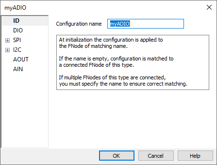
Before you can start using the ADIO to record IO signals, its global configuration has to be set. For more information refer to Network description.
1. Create a ADIO FNode via Hardware | Options | FNet and press Edit.
2. Configure your ADIO FNode.
The general configuration is set and you can continue with the following use cases.
|
If you are using ADIO in an automated setup, the necessary configuration can also be done in a script (e.g. Python). You can use FNet classes which can be used to control all the FNet nodes. |
Manual mode
When PWM_IN is a periodic pulse with 100 Hz frequency, manual mode is selected. The backlight illumination is determined by pulse width of the PWM_IN signal, i.e. the PWM_IN signal is “copied” to the PWM_OUT.
Automatic mode
When PWM_IN is a periodic pulse with 200 Hz frequency, automatic mode is selected. The backlight is automatically adjusted according to the input from the ambient light sensor. The ambient light sensor has a Voltage output, which is measured by the external ADC, and the ADC communicates with the target controller via SPI.
|
ADIO cannot be used as an SPI master, only as an SPI analyzer. |
Observing and recording digital signals
One of the simplest use cases for an ADIO is observing and recording digital signals (e.g. GPIO output pins of the target) and displaying them synchronously to the program execution trace in the Analyzer window.
The DIO pins of the ADIO are connected to the desired target board pin, and the logical state of the pin can be observed in winIDEA (via HIL Monitor in real-time, or via the Analyzer window in the recording) or it can be read in a script (e.g. Python script, using the appropriate API calls of the winIDEA SDK).
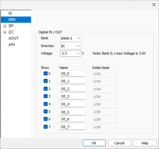
DIN configuration
ADIO DIO bank has to be configured.
1. Select DIO Bank 1 is selected.
2. Direction is chosen as an input.
3. Voltage level is set to 3.3V.
4. Select one signal 0.
The signal can also be renamed (PWM_OUT_BACKLIGHT), for more convenient viewing in either HIL monitor or Analyzer window. The configuration window is shown in the figure below:
|
Refer to DIO topic for more information. |
Alternative configuration (via SDK)
If you are using ADIO in an automated setup, the necessary configuration can also be done in a script (e.g. Python). Aside from CFNetController, for the digital IOs, CFNetDIOController should also be used to configure and control the DIOs of the ADIO module. The example provided on the CFNetDIOController page demonstrates how to configure and use the SDK for this purpose.
Controlling digital signals
A similar use case for an ADIO is controlling digital signals (e.g. GPIO input pins of the target). The same signals are simultaneously being recorded, synchronously to the application execution trace, and displayed in the Analyzer window. In this case the DIO pins of the ADIO are connected to the desired signals on the target board, and the signals can be controlled from winIDEA (via the HIL monitor plugin or the pattern generator) or by a script (e.g. Python script, using the appropriate API calls of the winIDEA SDK) during an active debug session.
DOUT Configuration
First, the ADIO DIO bank must be configured properly. For this use case, DIO Bank 0 is selected, direction is chosen as an output, and the voltage level is set to 3.3V. You can also set the initial signal value, which will be set on the pin at debug session start. Only one signal is used, and therefore chosen to be displayed. The signal can also be renamed (PWM_IN_MODE), for more convenient viewing in either HIL monitor or Analyzer window. The configuration window is shown in the figure below:
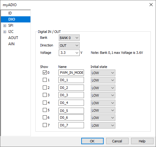
|
Refer to DIO topic for more information. |
Alternative configuration (via SDK)
If you are using ADIO in an automated setup, the necessary configuration can also be done in a script (e.g. Python). Aside from CFNetController, for the digital IOs, CFNetDIOController should also be used to configure and control the DIOs of the ADIO module. The example provided on the CFNetDIOController page demonstrates how to configure and use the SDK for this purpose.
Pattern Generator
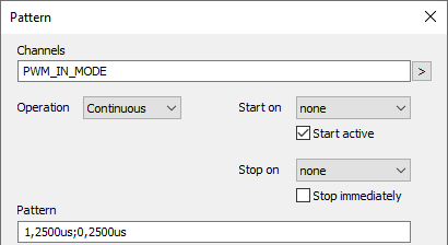
The PWM_IN_MODE is a signal which is generated by ADIO, and is used to configure the mode of operation in the target software. If the target software recognizes a square wave with a frequency of 100Hz, it will be set to Manual mode and as such, it will replicate the PWM_IN_MODE signal to its output - the PWM_OUT_BACKLIGHT signal.
Alternatively, if it recognizes a 200Hz square wave, it will enter the Automatic mode, in which it will take into account the data read from the SPI bus, to set the PWM duty cycle on the PWM_OUT_BACKLIGHT signal.
The PWM_IN_MODE signal can be generated using the FNet trigger system but the Pattern Generator offers a more elegant solution. A time dependent pattern will be generated to represent a square wave, which ADIO will generate on the selected channel. This pattern will start active (it will not wait on a trigger) and will be repeated continuously for as long the debug session is active. The configuration to achieve this is shown in the figure below:
|
Refer to Pattern Generator topic for more information. |
SPI Network traffic sniffing
The Serial Peripheral Interface (SPI) is a synchronous serial communication interface specification used for short-distance communication.
There are four SPI interface signals:
•MISO (Master Input Slave Output)
•MOSI (Master Output Slave Input)
•SCK (Serial Clock)
•CS/SS (Chip Select or Slave Select).
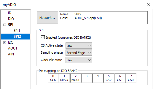
Information is transferred between Master and Slave on defined clock edge when CS/SS is in active state (if CS/SS is used). Active state of Chip Select (LOW or HIGH) is configurable. Using digital inputs, an optional SPI protocol analyzer is available for easy monitoring of two SPI interfaces within the embedded system either in standalone operation or in conjunction with the program execution. SPI protocol analyzer modules (SPI1, SPI2) are by default disabled because they consume digital I/O connectors or BANKS as specified in winIDEA. Note that if SPI1 is enabled it consumes DIO BANK0, and if SPI2 is enabled it consumes DIO BANK2.
SPI Configuration
First, the ADIO DIO bank must be configured properly. For this use case, DIO Bank 2 is used as the SPI sniffer. The SPI settings are configured according to the SPI communication that you are recording. In the case of our ADC, the settings are shown in the figure below. Pin mapping of the DIO Bank 2 is shown in the configuration window to accommodate easier connection to the SPI signals.
|
Refer to SPI topic for more information. |
In the Network section SPI protocol description can be specified. In this simple use case, MOSI messages are always expected to consist of a command and a repeated command, 2B each (named COMMAND_1 and COMMAND_2), with two possible values 0x428B (read channel 0) or 0x528B (read channel 1).
MISO messages are always formatted as following:
•12 bits: raw data which represents the conversion result
•4 bits: reserved
•16 bits: repeated command from MOSI
<!-- Defining a decoder for a new device.--> |
|
Refer to SPI protocol description format topic for more information. |
Alternative configuration (via SDK)
If you are using ADIO in an automated setup, the necessary configuration can also be done in a script (e.g. Python). Aside from the previously mentioned CFNetController, for the SPI Analyzer, CFNetSPIController should also be used to configure and control the DIOs of the ADIO . The example provided on the CFNetSPIController page demonstrates how to configure and use the SDK for this purpose.
Controlling external analog signals
With two available 12-bit resolution analog output channels (AOUT0 and AOUT1) you can control the external analog voltages in the range of ±5V. The outputs have a drive capability of 35mA and 30pF load, and are protected with a 33Ω serial termination.
|
Before connecting the AOUT0/AOUT1 channels, make sure that the GND potential of the AOUT0/AOUT1 connectors is connected to the GND potential of the embedded system first. Then connect the AOUT0/AOUT1 pins accordingly. |

The voltage level on the AOUT pins can be controlled from winIDEA (manually via HIL Monitor) or by a script (e.g. Python script, using the appropriate API calls from winIDEA SDK).
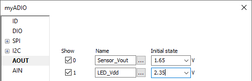
AOUT Configuration
This use case uses both AOUT channels. AOUT1 (renamed LED_Vdd) is used to supply an LED, whose illumination is measured by the sensor connected to our ADC Channel 1. AOUT0 (renamed Sensor_Vout) is used to emulate the sensor voltage output and is connected to our ADC Channel 0. You can also choose the initial state, which will be set at the start of the debug session.
|
Refer to AOUT topic for more information. |
Alternative configuration (via SDK)
If you are using ADIO in an automated setup, the necessary configuration can also be done in a script (e.g. Python). Aside from the CFNetController, the CFNetAOutController should also be used to configure and control the DIOs of the ADIO module. The example provided on the CFNetAOutController page demonstrates how to configure and use the SDK for this purpose.
Observing and recording external analog signals
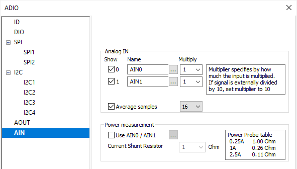
ADIO features two analog inputs, with input impedance 530kOhm / 8pF, 12-bit resolution, input range ±5V, max. sampling rate 12 MHz. Using standard oscilloscope probes, you can connect two analog inputs, AIN0 and AIN1, to the embedded system points where you want to measure or record analog signals. The measured voltage can be displayed in winIDEA (HIL Monitor) or read by a script (e.g. a Python script, using appropriate API calls from the winIDEA SDK).
AIN Configuration
For this use case you can use 1 AIN channel AIN0) to measure the output voltage of the illumination sensor. The same voltage is connected to the channel 1 of the external ADC, and the measurement result of the ADC is read out by the target via SPI bus. The settings are shown in the figure below. Multiply factor relates to the external division of the signal (as typically present on the standard oscilloscope probes). Additionally, an optional running average of the signal is featured, to smoothen the measured signal variations.
|
Refer to AIN and Power Probe measurement for more information. |
Alternative configuration (via SDK)
If you are using ADIO in an automated setup, the necessary configuration can also be done in a script (e.g. Python). Aside from the CFNetController, the CFNetAInController should also be used to configure and control the DIOs of the ADIO. The example provided on the CFNetAInController page demonstrates how to configure and use the SDK for this purpose.
Configuring the FNet operation for Analyzer recording
If you want to display the ADIO signals in the Analyzer recording, in parallel with the program execution or data trace, you also need to configure the FNet Operation options via Hardware | FNet Operation.
Qualifier
Primarily, you need to enable every submodule that you wish to record by setting the appropriate Qualifier setting to either enable the recording at the start of the Analyzer session, or to Enable/Disable the recording at a certain event, such as:
•Trace trigger
•RunSync
•StopSync or
•One of the 7 counter triggers available through the ADIO.
Each ADIO submodule page features a Qualifier button at the top, which prompts you to configure the following:
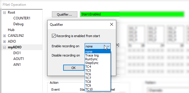
In the following use cases the recording of all submodules (DI, DO, SPI and AIN) will begin at the start of the Analyzer recording:
•DIO
•SPI
•AOUT
•AIN
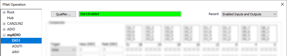
DIO
Once Start:Enabled is selected in the Qualifier section, you also need to select what to record in the Analyzer recordings. In this case select Enabled Inputs and Outputs.
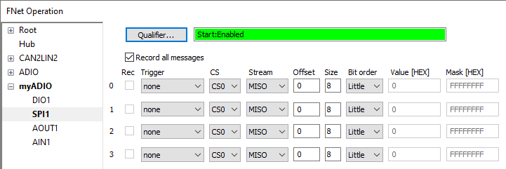
SPI
Once you select Start:Enabled in the Qualifier section, you also need to select what to record in the Analyzer recordings. In this select Record all messages. Alternatively, a Trigger can be generated when a message on the selected CS and Stream is recorded.
|
Refer to SPI topic for more information. |
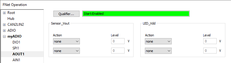
AOUT
With current implementation, AOUT signals cannot be recorded in the Analyzer. However, AOUT channels can respond to actions (e.g. when a certain Trigger line is active, set voltage to X.Y V).
|
Refer to AOUT topic for more information. |
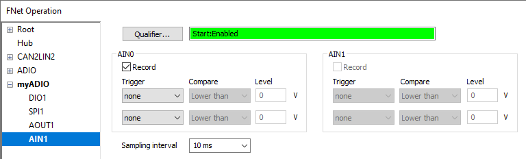
AIN
Once Start:Enabled is selected in the Qualifier section, you also need to select what to record in the Analyzer recordings. Aside from that, you can choose which channel to record, but you can also generate a Trigger once the value on the selected channel reaches the set threshold.The configuration window is shown below:
|
Refer to AIN topic for more information. |
winIDEA SDK Example
This Python example allows you to setup and configure the ADIO, and offers an on-the-fly text based interactive menu, to change the parameters of the ADIO inputs and outputs.